


Quick Research
Generate reliable direction feasibility study reports for your R&D in just a few steps.

Technical Q&A
Discover and master advanced knowledge NOW. Basics, ideas, possibilities, all at once.

Find Solutions
As an expert in R&D theories, this can generate solutions to your technical problems instantly.

Evaluate Feasibility
Analyze your overall solution with one click, know your potential R&D risks in advance.

Monitor Landscape
Get weekly tech updates, stay abreast of the latest tech innovations and key insights.
Computer room inspection camera and inspection method
A computer room and camera technology, applied in the computer field, can solve the problem that the monitoring of the computer room is difficult to monitor blind spots, etc., and achieve the effect of rich inspection routes and single compensation angle
- Summary
- Abstract
- Description
- Claims
- Application Information
AI Technical Summary
Problems solved by technology
Method used
Image

Examples
specific Embodiment approach 1
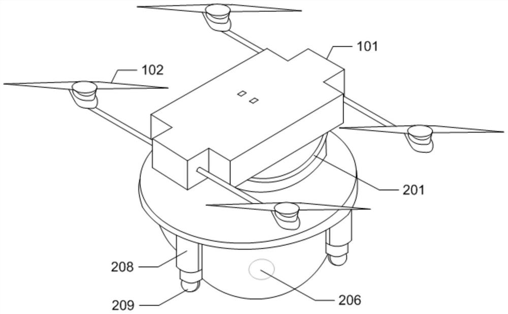
[0035] Specific implementation mode one: the following combination figure 1 Describe this embodiment, the computer room inspection camera described in this embodiment includes a charging stand, a flight unit and a monitoring unit; the charging stand is set on the roof of the computer room, and the flying unit and the monitoring unit are fixed together and sucked on the charging stand ;
[0036] The flight unit includes an upper connecting plate 101, four propellers 102 are arranged symmetrically on both sides of the upper connecting plate 101; the upper surface of the upper connecting plate 101 is provided with a charging electrode point matching the charging base; the upper connecting plate 101 is provided with a The upper layer electromagnet 103 is used to attract and engage with the iron block of the charging stand; the upper layer connecting plate 101 is provided with an iron block near the lower surface, and the upper layer connecting plate 101 is also provided with a mai...
specific Embodiment approach 2
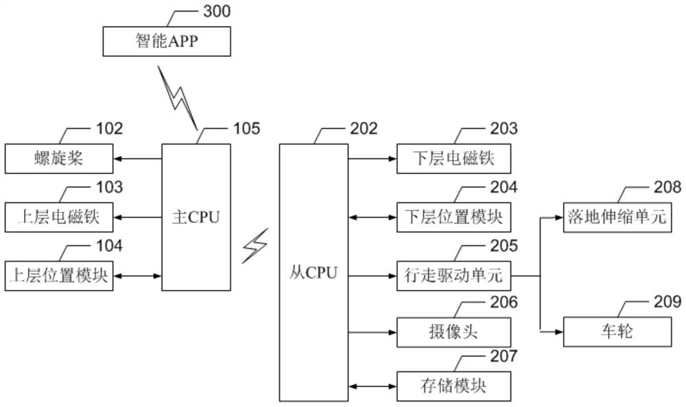
[0047] Specific implementation mode two: the following combination figure 2 To illustrate this embodiment, the computer room inspection method described in this embodiment includes two types: flight inspection and ground inspection, both of which are controlled by the smart APP 300 to send instructions. It can be scheduled inspection, or it can be manually sent instructions to inspect at any time.
[0048] Flight inspection steps:
[0049] Step 1, the smart APP300 sends the flight inspection command to the main CPU105;
[0050] Step 2, after the main CPU 105 accepts the flight inspection instruction, firstly start the propeller 102;
[0051] Step 3, the main CPU 105 releases the upper layer electromagnet 103, so that the flying unit is separated from the charging stand;
[0052] Step 4, the flight unit carries the monitoring unit along with the flight inspection planning route in the computer room for inspection, and the location information of the flight inspection is det...
PUM
 Abstract
Description
Claims
Application Information
 - R&D Engineer
- R&D Manager
- IP Professional
- Industry Leading Data Capabilities
- Powerful AI technology
- Patent DNA Extraction
Browse by: Latest US Patents, China's latest patents, Technical Efficacy Thesaurus, Application Domain, Technology Topic, Popular Technical Reports.
© 2024 PatSnap. All rights reserved.Legal|Privacy policy|Modern Slavery Act Transparency Statement|Sitemap|About US| Contact US: help@patsnap.com