
Camera calibration method, system and equipment suitable for driving equipment

A technology for driving equipment and calibration methods, applied in neural learning methods, image enhancement, image analysis, etc., which can solve the problems of large camera positioning errors and large positioning errors

Pending Publication Date: 2021-05-25
SHANGHAI ZHENHUA HEAVY IND
View PDF0 Cites 6 Cited by
  • Summary
  • Abstract
  • Description
  • Claims
  • Application Information

AI Technical Summary

Problems solved by technology

[0003] The applicant's research found that in the prior art, the camera of the driving equipment has a problem of large positioning error during use after calibration
[0004] The purpose of the present invention is to solve the problem in the prior art that the camera of the driving device has a large positioning error during use

Method used


Image

  • Camera calibration method, system and equipment suitable for driving equipment
  • Camera calibration method, system and equipment suitable for driving equipment
  • Camera calibration method, system and equipment suitable for driving equipment

Examples


Embodiment Construction

[0024] The embodiments of the present invention are described below by specific embodiments, and those skilled in the art can easily understand other advantages and effects of the present invention from the contents disclosed in this specification. Although the description of the invention will be presented in conjunction with the preferred embodiment, this does not mean that the features of the invention are limited to this embodiment. On the contrary, the purpose of introducing the invention in conjunction with the embodiments is to cover other options or modifications that may be extended based on the claims of the invention. The following description will contain numerous specific details in order to provide a thorough understanding of the present invention. The invention may also be practiced without these details. Furthermore, some specific details will be omitted from the description in order to avoid obscuring or obscuring the gist of the present invention. It should...


PUM


Abstract

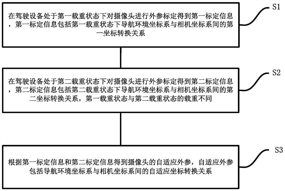
The invention discloses a camera calibration method suitable for driving equipment, and the method comprises the following steps: carrying out the external parameter calibration of a camera when the driving equipment is in a first load state, and obtaining first calibration information, wherein the first calibration information comprises a first coordinate conversion relation between a navigation environment coordinate system and a camera coordinate system in the first load state; when the driving equipment is in a second load state, performing external parameter calibration on the camera to obtain second calibration information, the second calibration information comprising a second coordinate conversion relation between the navigation environment coordinate system and the camera coordinate system in the second load state, and loads in the first load state and the second load state being different; and obtaining adaptive external parameters of the camera according to the first calibration information and the second calibration information. By adopting the technical scheme, the positioning precision of the camera is improved. The invention further provides a camera calibration system suitable for the driving equipment and computing equipment.

Description

technical field [0001] The present invention relates to the technical field of driving equipment, and in particular, to a method, system and equipment for calibrating a camera of a driving equipment. Background technique [0002] At present, in the field of driving equipment, especially for autonomous driving equipment, such as autonomous driving vehicles, it is often necessary to install cameras for detecting positioning markers for navigation. Therefore, it is necessary to calibrate the relevant external parameters of the camera to obtain the coordinate transformation relationship between the camera coordinate system of the camera and the vehicle body coordinate system, as well as the coordinate transformation relationship between the camera coordinate system and the navigation environment coordinate system (ie, the world coordinate system). The coordinate transformation relationship between the camera coordinate system and the vehicle body coordinate system is further obt...

Claims


Application Information

Patent Timeline
Patent Type & Authority Applications(China)
IPC IPC(8): G06T7/80G06T7/70G06N3/04G06N3/08
CPCG06T7/80G06T7/70G06N3/04G06N3/08G06T2207/30256G06T2207/20081
Inventor 吕刚晓单磊吴翔茅时群欧阳乐刘春明王全宇刘国辉
Owner SHANGHAI ZHENHUA HEAVY IND
Learn More