
Compact range antenna test system

A testing system and a technology of constricting field, which are applied to antenna radiation patterns, measuring devices, measuring electrical variables, etc., can solve the problem of increasing the diameter of the single-reflector constricting field reflector, increasing the difficulty and manufacturing cost of paraboloid processing, and the inability of large-diameter paraboloids. Problems such as whole block processing and forming, to achieve the effect of increasing the quiet zone space and improving the accuracy

Pending Publication Date: 2021-05-25
FRAGRANT MOUNTAIN MICROWAVE CO LTD
View PDF0 Cites 7 Cited by
  • Summary
  • Abstract
  • Description
  • Claims
  • Application Information

AI Technical Summary

Problems solved by technology

However, in the existing improvement methods, the improvement of the edge processing method cannot fully compensate the parabolic aperture field distribution, and the feed source radiation also has a large taper, so the utilization rate of the single-mirror contracted field aperture is still lower than 60%. As the size of the antenna under test increases, the size of the required quiet zone increases, so that the diameter of the single-mirror compact field mirror is also forced to increase significantly, which will undoubtedly increase the difficulty of processing the paraboloid and the manufacturing cost. Whole block processing and molding

Method used


Image

  • Compact range antenna test system
  • Compact range antenna test system
  • Compact range antenna test system

Examples


Embodiment Construction

[0025] Embodiments of the present invention are described in detail below, examples of which are shown in the drawings, wherein the same or similar reference numerals designate the same or similar elements or elements having the same or similar functions throughout. The embodiments described below by referring to the figures are exemplary only for explaining the present invention and should not be construed as limiting the present invention.

[0026] Those skilled in the art can understand that, unless otherwise stated, the word "comprising" used in the description of the present invention refers to the presence of the features, integers, steps, operations, parts / components and / or components, but does not exclude the presence or Add one or more other features, integers, steps, operations, parts / parts, components and / or groups thereof. It should be understood that when we refer to a part / component as being "connected" to another part / component, it may be directly connected to t...


PUM


Abstract

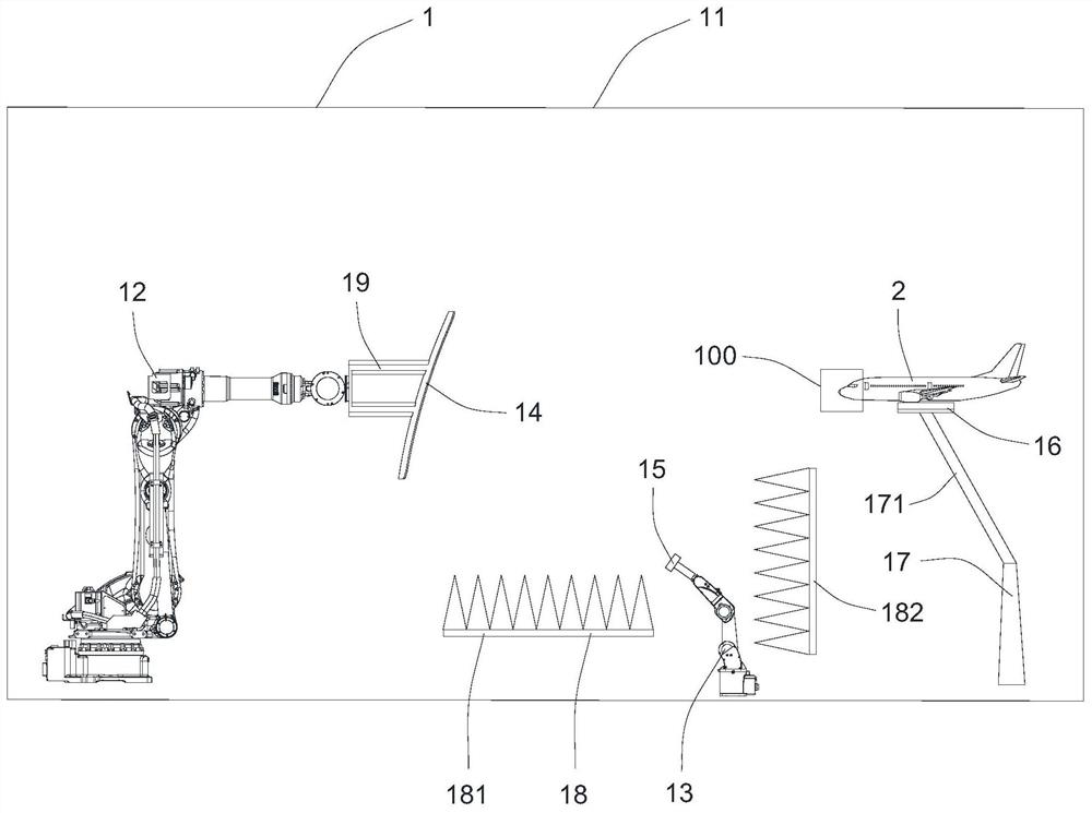
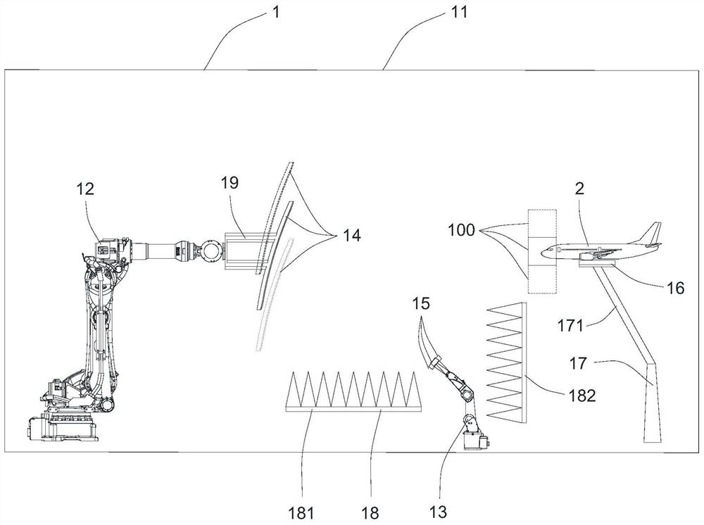
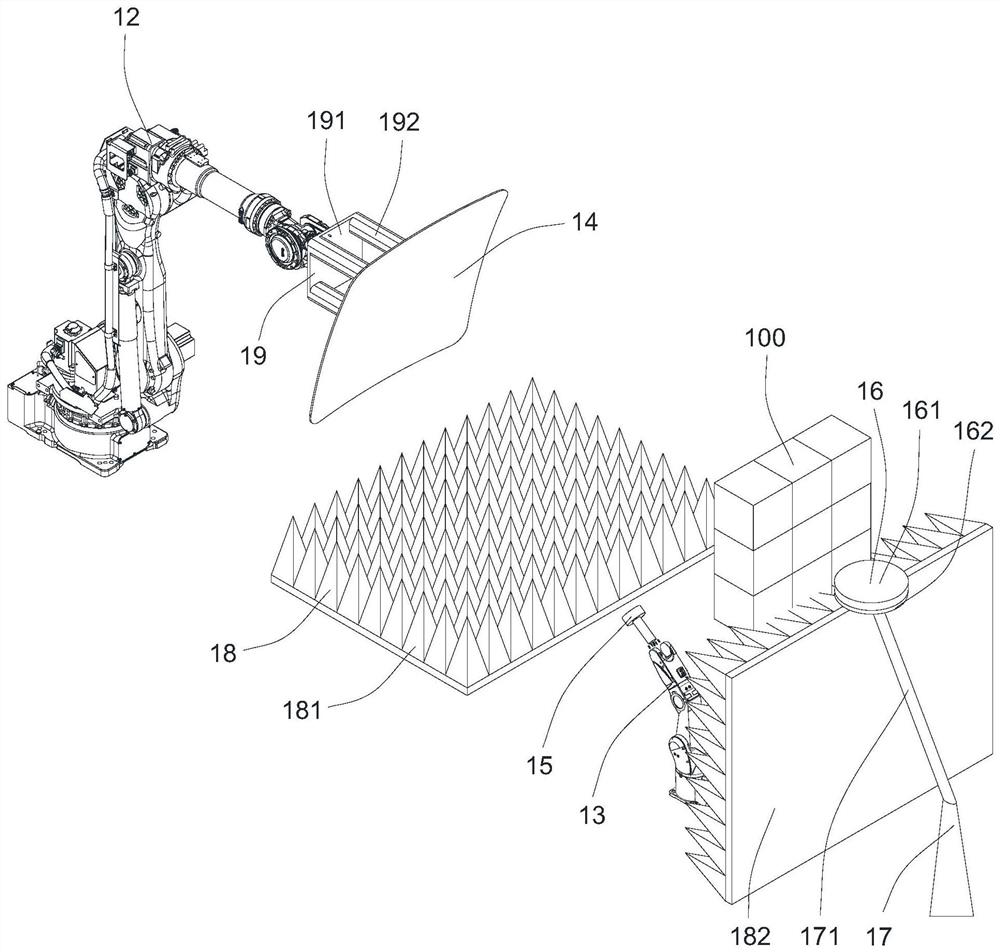
A compact range antenna test system provided by the present invention comprises a microwave anechoic chamber, and a first manipulator, a second manipulator, a reflector and a feed source which are all arranged in the microwave anechoic chamber, the reflector is arranged on the first manipulator, the feed source is arranged on the second manipulator and faces the reflector, the reflector is used for focusing emergent waves emitted by the feed source into plane waves and reflecting the plane waves to a to-be-tested piece to form a quiet zone, the first manipulator can drive the reflector to move, and the second manipulator can drive the feed source to move according to the moving position of the reflector so as to translate the quiet zone. According to the compact range antenna test system provided by the invention, the reflector and the feed source are respectively driven by the first manipulator and the second manipulator to move, and translation of the quiet zones can be realized by combining real-time matching and alignment of the reflector and the feed source, so that a plurality of quiet zones which can be mutually spliced are formed, the space of the quiet zones is multiplied, and the test performance is improved.

Description

technical field [0001] The invention relates to the field of antenna testing, in particular to a compact field antenna testing system. Background technique [0002] At present, since the indoor far-field distance is difficult to meet the test of large-aperture antennas, especially high-frequency and millimeter-wave antennas, it is generally necessary to use indirect far-field test methods for testing. For example, the compact field antenna test method mainly uses a lens or a parabola to make the rays emitted by a point source or a line source parallel to the antenna under test, and generates a quasi-plane wave radiation field in a small space to approximate the simulated plane wave radiation conditions. The measurement satisfies the antenna measurement far-field condition. [0003] In the compact field antenna test system, the approximate plane wave area formed by the reflector is called the quiet zone. The electromagnetic field in the quiet zone has small amplitude and pha...

Claims


Application Information

Patent Timeline
Patent Type & Authority Applications(China)
IPC IPC(8): G01R29/10
CPCG01R29/10G01R29/105
Inventor 卜景鹏东君伟马向华梁有宁
Owner FRAGRANT MOUNTAIN MICROWAVE CO LTD
Learn More