Agricultural timber pile automatic punching equipment

A technology for drilling equipment and stakes, which is applied to wood processing equipment, clamps, fixed drilling machines, etc., and can solve problems such as time-consuming, labor-intensive, and complicated locks

Pending Publication Date: 2021-05-25
侯毅
View PDF2 Cites 4 Cited by
  • Summary
  • Abstract
  • Description
  • Claims
  • Application Information

AI Technical Summary

Problems solved by technology

[0004] In order to overcome the need for farmers to manually hold the stakes for a long time, it takes a lot of effort. At the same time, the process for farmers to rotate the stakes to change the drilling position at intervals is cumbersome, and it takes a long time for farmers to completely drill the stakes. The wood chips are collected, and the farmers manually punch the stakes to cause positional deviation. The technical problem of the present invention is: to provide a method that can quickly punch the agricultural stakes and clamp the stakes at the same time. It is an automatic punching equipment for agricultural wood piles that is tightly fixed and can collect wood chips, thereby reducing the labor intensity of farmers.

Method used


Image

  • Agricultural timber pile automatic punching equipment
  • Agricultural timber pile automatic punching equipment
  • Agricultural timber pile automatic punching equipment

Examples


Embodiment 1

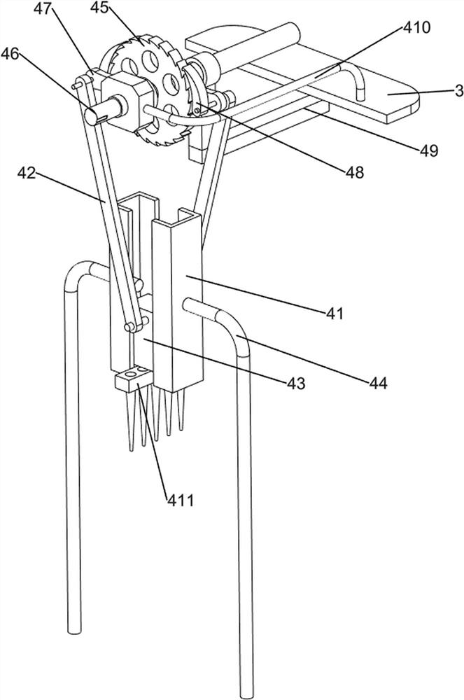
[0023] An automatic punching device for agricultural stakes, such as figure 1 As shown, it includes a base 1, a motor 2, a first support plate 3, a pressing mechanism 4 and a clamping mechanism 5. The rear end of the top of the base 1 is provided with a first support plate 3, and the middle of the top of the first support plate 3 is fixed by bolts. Connected with motor 2, motor 2 output shaft front end is equipped with pressing mechanism 4, base 1 top front and rear sides are symmetrically provided with clamping mechanism 5, and pressing mechanism 4 cooperates with clamping mechanism 5.

[0024] When the farmer needs to drill holes on the stake, the farmer first puts the stake on the clamping mechanism 5, and when the stake is on the clamping mechanism 5, the farmer needs to start the motor 2 to rotate, and the output shaft of the motor 2 rotates It will drive the downward pressure mechanism 4 to move downward, and the downward movement of the downward pressure mechanism 4 wil...

Embodiment 2

[0026] In a preferred embodiment of the present invention, as Figure 1-Figure 6 As shown, the pressing mechanism 4 includes a first slide rail 41, a rotating shaft 42, a first slider 43, a first support rod 44, a ratchet 45, a first rotating shaft 46, a first cam 47, a pawl 48, a fixed shaft 49. Fixed block 410 and drill bit 411, first support rods 44 are symmetrically arranged on the left and right sides of the top of the base 1, the tops of the two first support rods 44 are fixedly connected with the first slide rail 41, and the upper part of the front side of the first support plate 3 A fixed shaft 49 is installed, and the output shaft front end of the motor 2 is equipped with a first rotating shaft 46. The top of the fixed shaft 49 is rotated through the first rotating shaft 46. The front part of the first rotating shaft 46 is provided with a ratchet 45. On the first rotating shaft 46 First cams 47 are arranged at intervals, and ratchets 48 are installed on the two first ...


PUM


Abstract

The invention relates to punching equipment, in particular to agricultural timber pile automatic punching equipment. According to the agricultural timber pile automatic punching equipment, agricultural timber piles can be rapidly punched, meanwhile, the timber piles can be clamped and fixed, wood chips can be collected, and therefore the labor intensity of farmers is relieved. The agricultural timber pile automatic punching equipment comprises a base, a motor and a first supporting plate; the first supporting plate is arranged at the rear end of the top of the base; and the motor is fixedly connected to the middle of the top of the first supporting plate through bolts. According to the agricultural timber pile automatic punching equipment, a downward pressing mechanism is arranged, and the downward pressing mechanism is matched with a clamping mechanism, so that clamping and punching work of the timber piles can be achieved; the downward pressing mechanism is matched with a shaking mechanism, so that timber pile sawdust particles can be collected; and the clamping mechanism is matched with an overturning mechanism, and interval overturning work of the timber piles can be achieved.

Description

technical field [0001] The invention relates to a punching device, in particular to an automatic punching device for agricultural stakes. Background technique [0002] With the development of social industrialization, traditional farming methods have been gradually replaced by industrialized production. For example, a kind of mushroom planting with wooden pile holes in agriculture, farmers generally need to drill holes in wooden piles in advance. The traditional way is for farmers to step on With dynamic drilling, farmers need to manually hold the stake for a long time and it takes a lot of effort. At the same time, the process of changing the drilling position by rotating the stake at intervals is more complicated, and it takes a long time for the farmer to completely drill the stake. The sawdust generated in the farm is collected, and the farmers manually punch the stakes, and the position will be shifted. [0003] Therefore, aiming at the above-mentioned prior art proble...

Claims


Application Information

Patent Timeline
IPC IPC(8): B27C3/02B25B5/14B25B5/16B27G3/00
CPCB27C3/02B25B5/14B25B5/163B27G3/00
Inventor 侯毅
Owner 侯毅
Why Eureka
Try Eureka