Perforating equipment
A technology of drilling equipment and drill, applied in the field of drilling machines, can solve the problems of affecting the observation of pipe fittings, affecting the surrounding environment, and misalignment of the punching needle, so as to protect health, prevent debris from splashing, and prevent misalignment. Effect
- Summary
- Abstract
- Description
- Claims
- Application Information
AI Technical Summary
Problems solved by technology
Method used
Image
Examples
Embodiment 1
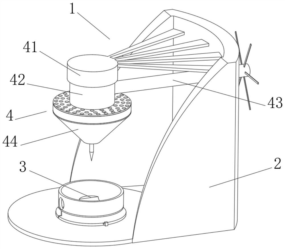
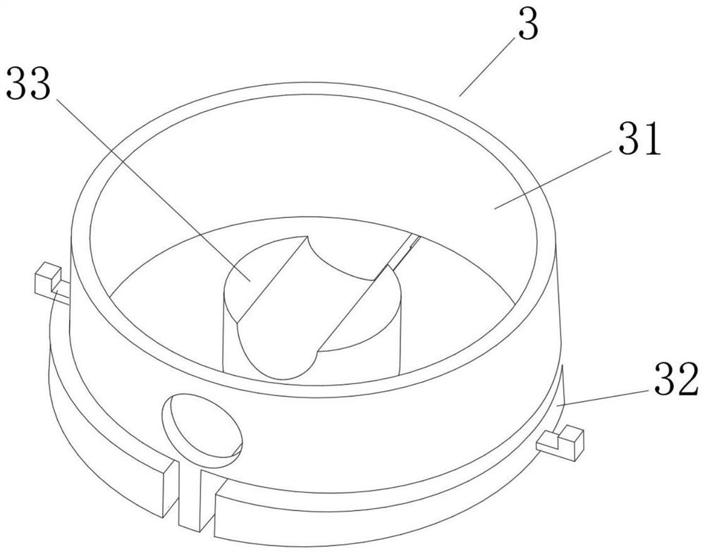
[0036] see Figure 1-2 , the present invention provides a technical solution: a punching device, comprising a punching device body 1 composed of a support 2, a collection mechanism 3 and a punching mechanism 4, the bottom of the collection mechanism 3 is fixedly connected to the top of the support 2, The inside of the punching mechanism 4 is fixedly connected to the inside of the support 2 through a support rod. The collection mechanism 3 includes a collection frame 31. The bottom of the collection frame 31 is slidably connected with a magnetic block 32, and the bottom of the magnetic block 32 slides with the top of the support 2. Connection, the bottom of the collection frame 31 is fixedly connected with the top of the support 2, the top of the support 2 is fixedly connected with a deck 33, the deck 33 is located inside the collection frame 31, the punching mechanism 4 includes a driving mechanism 41, and the driving mechanism 41 The right side of the drive mechanism 41 is fi...
Embodiment 2
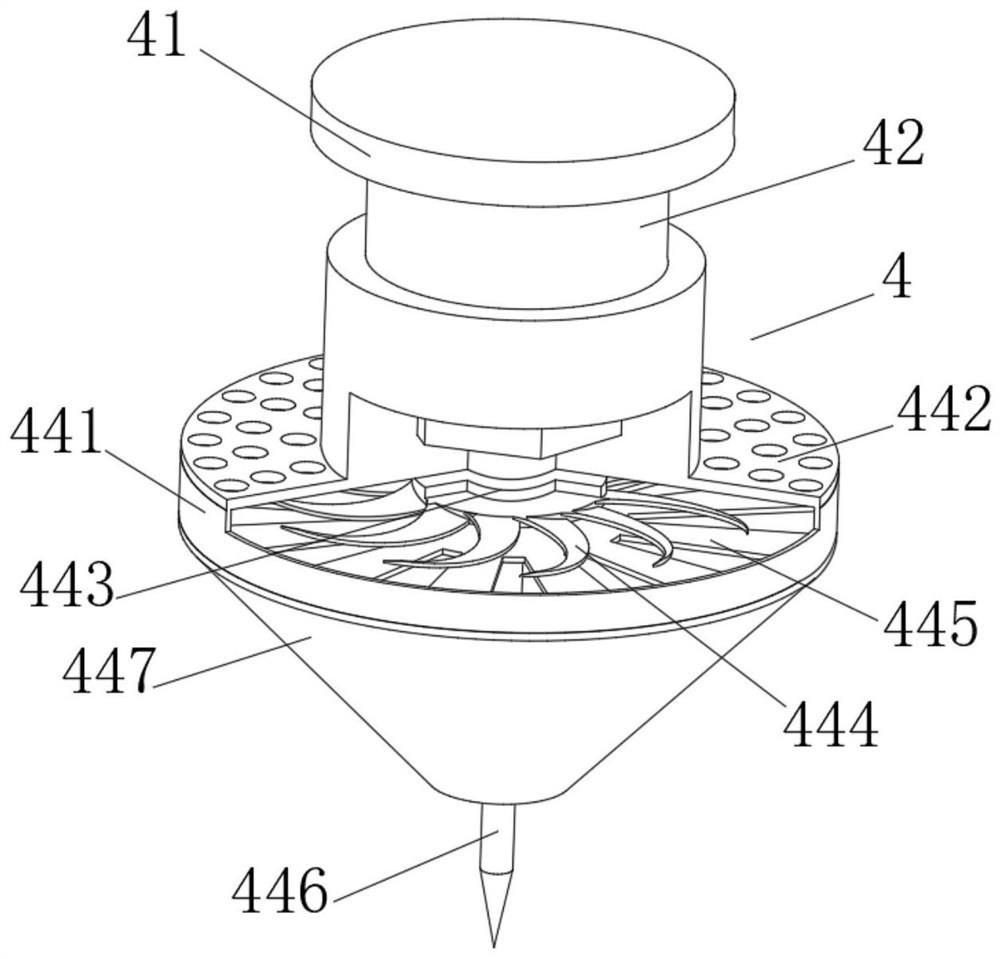
[0039] see Figure 1-4 , On the basis of Embodiment 1, the present invention provides a technical solution: the drill 44 includes a drilling frame 441, the top of the drilling frame 441 is fixedly connected with a suction plate 442, and the top of the suction plate 442 is connected with the telescopic mechanism The bottom of 42 is fixedly connected.
[0040] The inside of the suction plate 442 is rotatably connected with a bearing 443 , the top of the bearing 443 is rotatably connected with the inside of the telescopic mechanism 42 through a motor, and the motor is located inside the telescopic mechanism 42 .
[0041] The outer side of bearing 443 is fixedly connected with vane 444 , the inner wall of drilling frame 441 is fixedly connected with ventilating plate 445 , the bottom of bearing 443 is threadedly connected with punching pin 446 , and ventilating plate 445 is positioned at the just below of vane 444 .
[0042] The bottom of the drilling frame 441 is fixedly connect...
Embodiment 3
[0046] see Figure 1-5 , On the basis of Embodiment 1 and Embodiment 2, the present invention provides a technical solution: the blowing mechanism 449 includes an air guide tube 4491, the top of the air guide tube 4491 communicates with the inside of the wind collecting plate 447, and the bottom of the air guide tube 4491 It communicates with elastic tube 4492.
[0047] The outside of the elastic tube 4492 is provided with an elastic block 4493, and the side of the elastic block 4493 away from the elastic tube 4492 is fixedly connected with the inside of the air guide tube 4491. The bottom communicates with an air jet bag 4495.
[0048] The interior of the air jet bag 4495 is fixedly connected with a rebound rod 4496, and the bottom of the air jet bag 4495 is communicated with a diverging pipe 4497.
[0049] When in use, when the wind energy flows into the blowing mechanism 449, the air guide tube 4491 in the blowing mechanism 449 swings slightly, flows into the elastic tube...
PUM
 Abstract
Description
Claims
Application Information
 - R&D
- Intellectual Property
- Life Sciences
- Materials
- Tech Scout
- Unparalleled Data Quality
- Higher Quality Content
- 60% Fewer Hallucinations
Browse by: Latest US Patents, China's latest patents, Technical Efficacy Thesaurus, Application Domain, Technology Topic, Popular Technical Reports.
© 2025 PatSnap. All rights reserved.Legal|Privacy policy|Modern Slavery Act Transparency Statement|Sitemap|About US| Contact US: help@patsnap.com


