
In-mill screening and lifting device and vertical roller mill

A vertical roller mill and screening technology, applied in the direction of sieve, solid separation, chemical instruments and methods, etc., can solve the problems of increasing the load of the powder separation fan, increasing the consumption of mechanical energy, etc., to save mechanical energy, save energy, Easy to install and use

Pending Publication Date: 2021-05-25
NANJING XIPU CEMENT ENG GROUP
View PDF0 Cites 0 Cited by
  • Summary
  • Abstract
  • Description
  • Claims
  • Application Information

AI Technical Summary

Problems solved by technology

[0004] The object of the present invention is to provide a screening and lifting device in the mill and a vertical roller mill, which solves the problem that the vertical roller mill in the prior art needs to be equipped with a large-scale circulation hoist with high power, increases the fan load for powder selection, and also Increased mechanical energy consumption issues

Method used


Image

  • In-mill screening and lifting device and vertical roller mill
  • In-mill screening and lifting device and vertical roller mill
  • In-mill screening and lifting device and vertical roller mill

Examples


Embodiment Construction

[0024] It is easy to understand that, according to the technical solution of the present invention, those skilled in the art can propose multiple structural modes and implementation modes that can be replaced without changing the essence and spirit of the present invention. Therefore, the following specific embodiments and drawings are only exemplary descriptions of the technical solution of the present invention, and should not be regarded as the entirety of the present invention or as a limitation or restriction on the technical solution of the present invention.

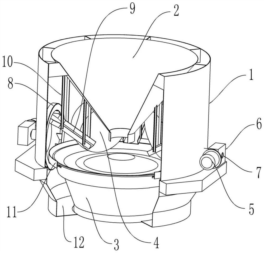
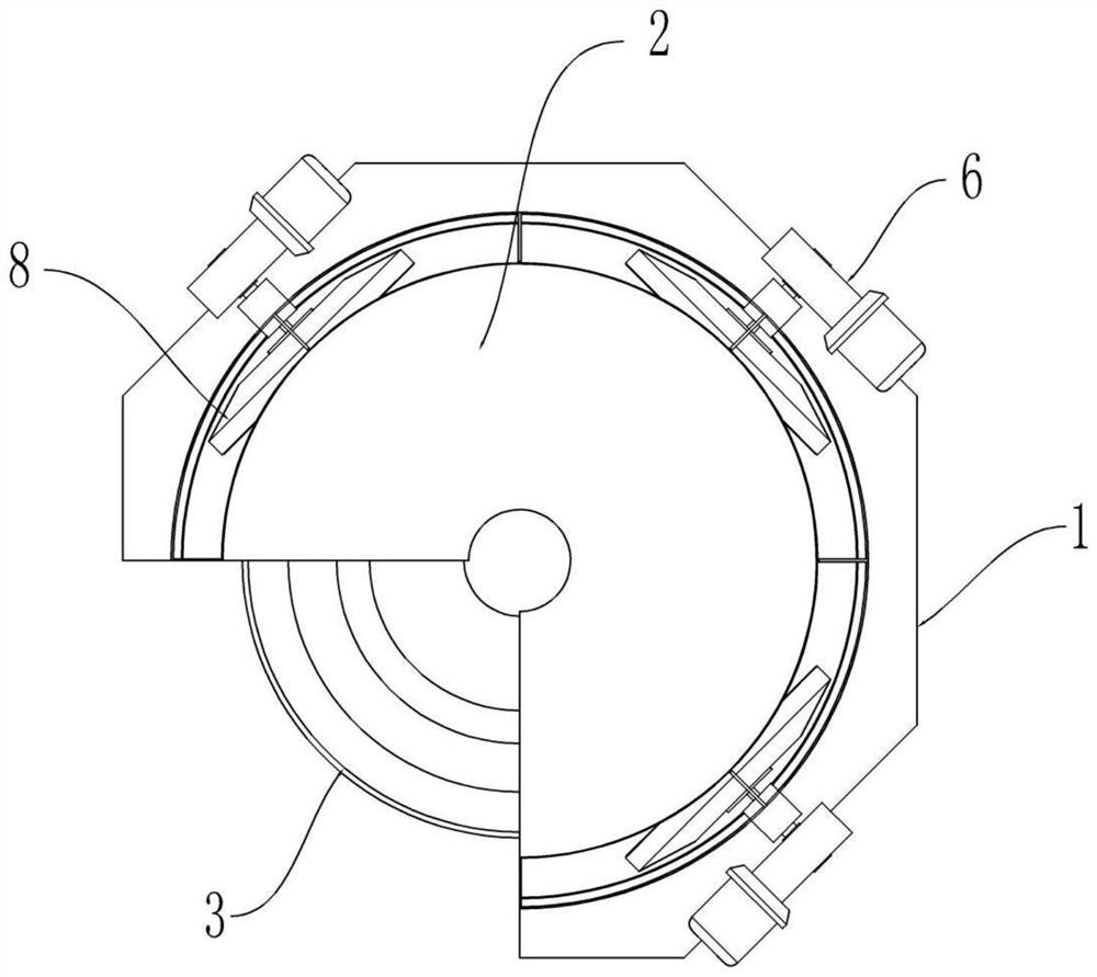
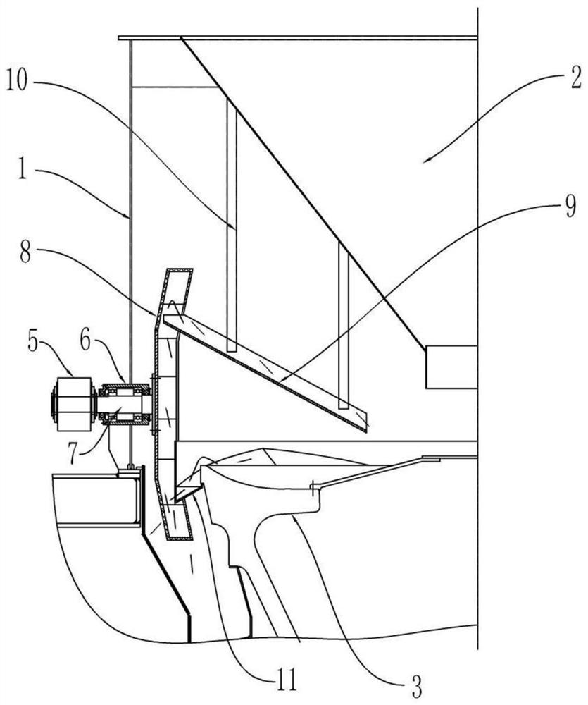
[0025] According to an embodiment of the present invention combined with Figures 1 to 8 show. A vertical roller mill, comprising a shell 1, a feeding cone 2, a grinding disc 3, a grinding roller 4, a mill hopper 12 and a screening and lifting device inside the mill. The blanking cone 2 is arranged inside the housing 1 to guide the inflow of materials; the millstone 3 is located below the outlet of the blanking c...


PUM


Abstract

The invention provides an in-mill screening and lifting device and a vertical roller mill. The in-mill screening and lifting device is applied to the vertical roller mill. The vertical roller mill comprises a shell, a grinding disc and a plurality of grinding rollers. The device comprises a collecting hopper, wherein the collecting hopper is arranged on the periphery of the grinding disc between the two adjacent grinding rollers, and a gap is formed between the inner side of the collecting hopper and the outer wall of the grinding disc; a rotary screen arranged on the outer side of the collecting hopper, wherein the bottom end part of the rotary screen is located below the collecting hopper, and the rotary screen is used for lifting materials discharged from the collecting hopper to the top end part of the rotary screen; a discharging chute, wherein the discharging chute is arranged above the grinding disc in a posture that the outer part is high and the inner part is low, and the top end part of the discharging chute is positioned under the top end part of the rotary screen; and a rotary screen driving part which is arranged on the outer side of the vertical roller mill and is in transmission connection with the rotary screen. The in-mill screening and lifting device and the vertical roller mill have the characteristics of a compact structure, convenience in installation and use, stability in operation and simplicity in maintenance. High economic value and social benefits are achieved in the aspects of energy conservation and emission reduction.

Description

technical field [0001] The invention relates to the technical field of grinding equipment, in particular to an in-mill screening and lifting device and a vertical roller mill. Background technique [0002] At present, in the production process of cement and other building materials industries, vertical roller mills have always occupied a huge market as final grinding equipment for raw materials, final products, and solid waste treatment. As the energy and environment requirements become more and more stringent, while using the vertical mill, the energy consumption of the vertical mill system is put forward higher requirements. [0003] Although the vertical roller mill has the characteristics of compact structure and low infrastructure costs, it is at a disadvantage compared with the roller press system in terms of energy consumption because its finished product transportation and most of the material circulation rely on wind power to lift. This has given birth to a new typ...

Claims


Application Information

Patent Timeline
Patent Type & Authority Applications(China)
IPC IPC(8): B02C15/00B02C23/00B02C23/12B02C23/16B07B1/08B07B1/42
CPCB02C15/00B02C23/16B02C23/12B02C23/00B07B1/08B07B1/42
Inventor 曹国锋赵建钱旺龙朱宽平陆小平
Owner NANJING XIPU CEMENT ENG GROUP
Learn More