Visible light communication method, device and storage medium
A visible light communication and visible light technology, applied in the field of communication, can solve problems such as time-consuming and complex collaborative focusing, and achieve the effect of simplifying the focusing process
- Summary
- Abstract
- Description
- Claims
- Application Information
AI Technical Summary
Problems solved by technology
Method used
Image
Examples
Embodiment 1
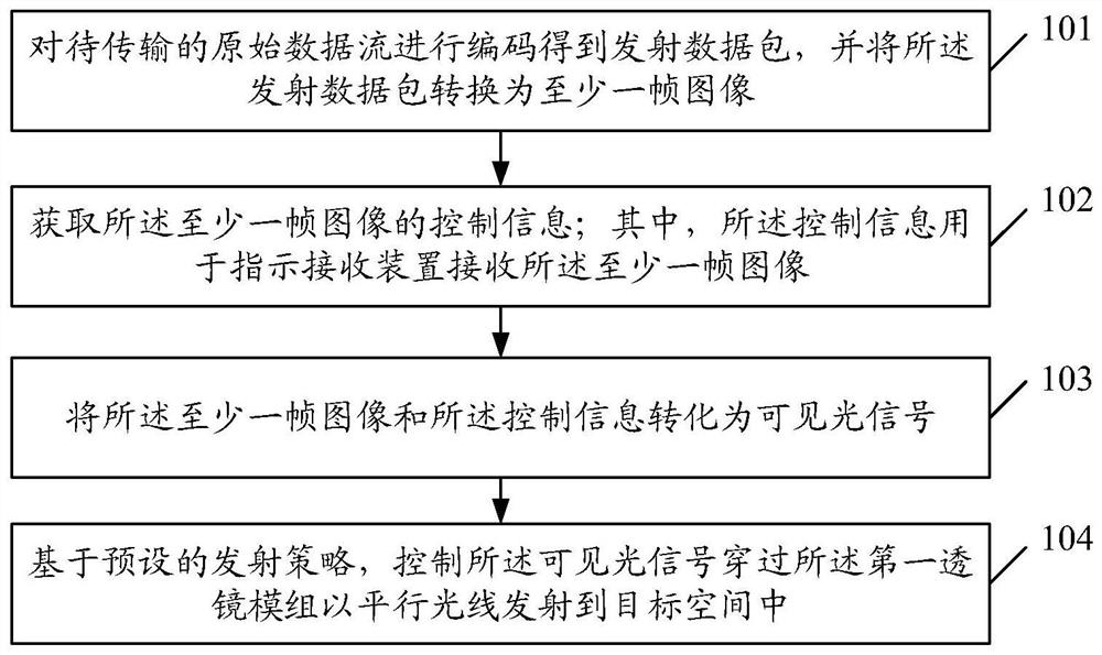
[0045] The embodiment of the present application provides a visible light communication method, figure 1 It is a schematic diagram of the first flow chart of the visible light communication method in the embodiment of the present application, as shown in figure 1 As shown, the method may specifically include:
[0046] Step 101: Encoding the original data stream to be transmitted to obtain a transmission data packet, and converting the transmission data packet into at least one frame of image;
[0047] Step 102: Acquire control information of the at least one frame of image; wherein, the control information is used to instruct the receiving device to receive the at least one frame of image;
[0048] Step 103: converting the at least one frame of image and the control information into a visible light signal;
[0049] Step 104: Based on a preset emission strategy, control the visible light signal to pass through the first lens module and emit parallel rays into the target space. ...
Embodiment 2
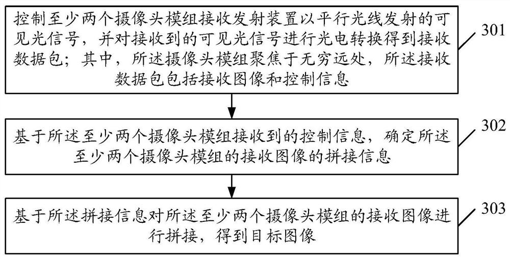
[0072] The embodiment of the present application provides a visible light communication method, image 3 It is a schematic diagram of the second flow chart of the visible light communication method in the embodiment of the present application, as shown in image 3 As shown, the method may specifically include:
[0073] Step 301: Control at least two camera modules to receive visible light signals emitted by the transmitting device in parallel light, and perform photoelectric conversion on the received visible light signals to obtain received data packets; wherein, the camera modules are focused at infinity, and the The receiving data packet includes receiving image and control information;
[0074] Step 302: Based on the control information received by the at least two camera modules, determine the mosaic information of the received images of the at least two camera modules;
[0075] Step 302: Based on the stitching information, stitch the received images of the at least two...
Embodiment 3
[0096] The embodiment of the present application also provides a transmitting device, such as Figure 4 As shown, the launcher includes:
[0097] The first lens module 401;
[0098] An image generation unit 402, configured to encode the original data stream to be transmitted to obtain a transmission data packet, and convert the transmission data packet into at least one frame of image;
[0099] A transmission control unit 403, configured to acquire control information of the at least one frame of image; wherein the control information is used to instruct the receiving device to receive the at least one frame of image;
[0100] a spatial light modulation unit 404, configured to convert the at least one frame of image and the control information into visible light signals;
[0101] The emission control unit 403 is further configured to control the visible light signal to pass through the first lens module 401 and emit parallel rays into the target space based on a preset emiss...
PUM
 Abstract
Description
Claims
Application Information
 - R&D
- Intellectual Property
- Life Sciences
- Materials
- Tech Scout
- Unparalleled Data Quality
- Higher Quality Content
- 60% Fewer Hallucinations
Browse by: Latest US Patents, China's latest patents, Technical Efficacy Thesaurus, Application Domain, Technology Topic, Popular Technical Reports.
© 2025 PatSnap. All rights reserved.Legal|Privacy policy|Modern Slavery Act Transparency Statement|Sitemap|About US| Contact US: help@patsnap.com


