
an autofocus system

An automatic focus and focal length technology, applied in the field of image sensors, can solve the problems of time occupation, long focusing time, and difficulty in obtaining asymmetric pixels for light, so as to ensure accuracy, simplify the focusing process, and shorten the focusing time. Effect

Active Publication Date: 2020-05-15
SHANGHAI INTEGRATED CIRCUIT RES & DEV CENT +1
View PDF5 Cites 0 Cited by
  • Summary
  • Abstract
  • Description
  • Claims
  • Application Information

AI Technical Summary

Problems solved by technology

[0006] However, when using the above-mentioned prior focusing method for optically asymmetrical pixels, it is difficult to obtain the relationship between the signal size and the focal length position of the optically asymmetrical pixels and takes up a lot of time, so the entire focusing time is still very long

Method used


Image

  • an autofocus system
  • an autofocus system
  • an autofocus system

Examples


Embodiment Construction

[0026] The specific embodiment of the present invention will be further described in detail below in conjunction with the accompanying drawings.

[0027] It should be noted that, in the following specific embodiments, when describing the embodiments of the present invention in detail, in order to clearly show the structure of the present invention for the convenience of description, the structures in the drawings are not drawn according to the general scale, and are drawn Partial magnification, deformation and simplification are included, therefore, it should be avoided to be interpreted as a limitation of the present invention.

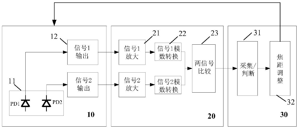
[0028] In the following specific embodiments of the present invention, please refer to figure 1 , figure 1 It is a structural block diagram of an autofocus system in a preferred embodiment of the present invention. Such as figure 1 As shown, an autofocus system of the present invention includes a signal acquisition and output module 10 , a signal ...


PUM


Abstract

The invention discloses an automatic focusing system, comprising: a signal acquisition and output module, used to collect and output two electrical signals formed by the conversion of each light asymmetric pixel in a pixel array; a signal amplification and comparison module, used to respectively Perform amplification and analog-to-digital conversion on the two electrical signals of each optically asymmetrical pixel, compare the two generated digital signals of each optically asymmetrical pixel, and output a comparison result with two binary numbers as the representative signal; The signal collection, judgment and adjustment module is used to sequentially collect the high-order or low-order numerical signals in the binary numbers of the binary numbers of the comparison results of the two digital signals of each optically asymmetrical pixel in each row or column of the pixel array to form a string of binary codes. Collect the signal, and judge whether the focal length is accurate through the binary code of the collected signal, so as to adjust the focal length of the lens accordingly. The invention can simplify the focusing process and further shorten the focusing time.

Description

technical field [0001] The present invention relates to the technical field of image sensors, and more particularly, to an autofocus system applied to an optically asymmetric pixel array. Background technique [0002] With the continuous development of CMOS technology and image sensor technology, CMOS image sensors are more and more widely used in electronic monitoring, navigation, transportation and other fields. However, with the continuous development of CMOS image sensor technology, the performance requirements of the CMOS image sensor are also getting higher and higher. [0003] Focusing speed is an important indicator of the CMOS image sensor, the shorter the focusing time, the better the performance of the CMOS image sensor. [0004] Among the several existing focusing methods, the algorithm design of the contrast method focusing technology is more difficult; the contrast focusing method needs to complete a complete focus scan every time it focuses, and the focusing ...

Claims


Application Information

Patent Timeline
Patent Type & Authority Patents(China)
IPC IPC(8): H04N5/232H04N5/235
CPCH04N23/67H04N23/73
Inventor 曾夕何学红杨海玲段杰斌严慧婕
Owner SHANGHAI INTEGRATED CIRCUIT RES & DEV CENT
Learn More