Automatic machining process for fan stand column

An automatic processing and column technology, applied in metal processing, metal processing equipment, metal processing machinery parts, etc., can solve the problems of large investment in equipment, long process, processing errors, etc., and achieve the effect of improving efficiency

Inactive Publication Date: 2021-05-21
钟起官
View PDF0 Cites 0 Cited by
  • Summary
  • Abstract
  • Description
  • Claims
  • Application Information

AI Technical Summary

Problems solved by technology

[0003] However, when the existing fan column processing device processes the outer tube and the inner tube of the column, the outer tube and the inner tube of the column are processed manually, including the following procedures. First, the inner tube and the outer tube are cut to the required length, and then transferred to the punching machine to punch the inner tube and the outer tube. Then, the inner tube and the outer tube need to be transferred to the punching machine to punch the double buckle. After punching the double buckle, the inner tube must be punched The inner and outer circles at both ends are shaped on the shaping machine. The entire processing process needs to be transferred between multiple equipments. The investment in equipment takes up a lot of space, and the efficiency of manual processing is low and it is easy to cause processing errors during processing. , affecting the subsequent use of the outer tube and inner tube of the column, the process is long and complicated

Method used


Image

  • Automatic machining process for fan stand column
  • Automatic machining process for fan stand column
  • Automatic machining process for fan stand column

Examples


Embodiment Construction

[0045] The technical solutions of the present invention will be clearly and completely described below in conjunction with the accompanying drawings. Apparently, the described embodiments are some of the embodiments of the present invention, but not all of them.

[0046] The components of the embodiments of the invention generally described and shown in the figures herein may be arranged and designed in a variety of different configurations. Accordingly, the following detailed description of the embodiments of the invention provided in the accompanying drawings is not intended to limit the scope of the claimed invention, but merely represents selected embodiments of the invention.

[0047] Based on the embodiments of the present invention, all other embodiments obtained by persons of ordinary skill in the art without making creative efforts belong to the protection scope of the present invention.

[0048] In the description of the present invention, it should be noted that the...


PUM


Abstract

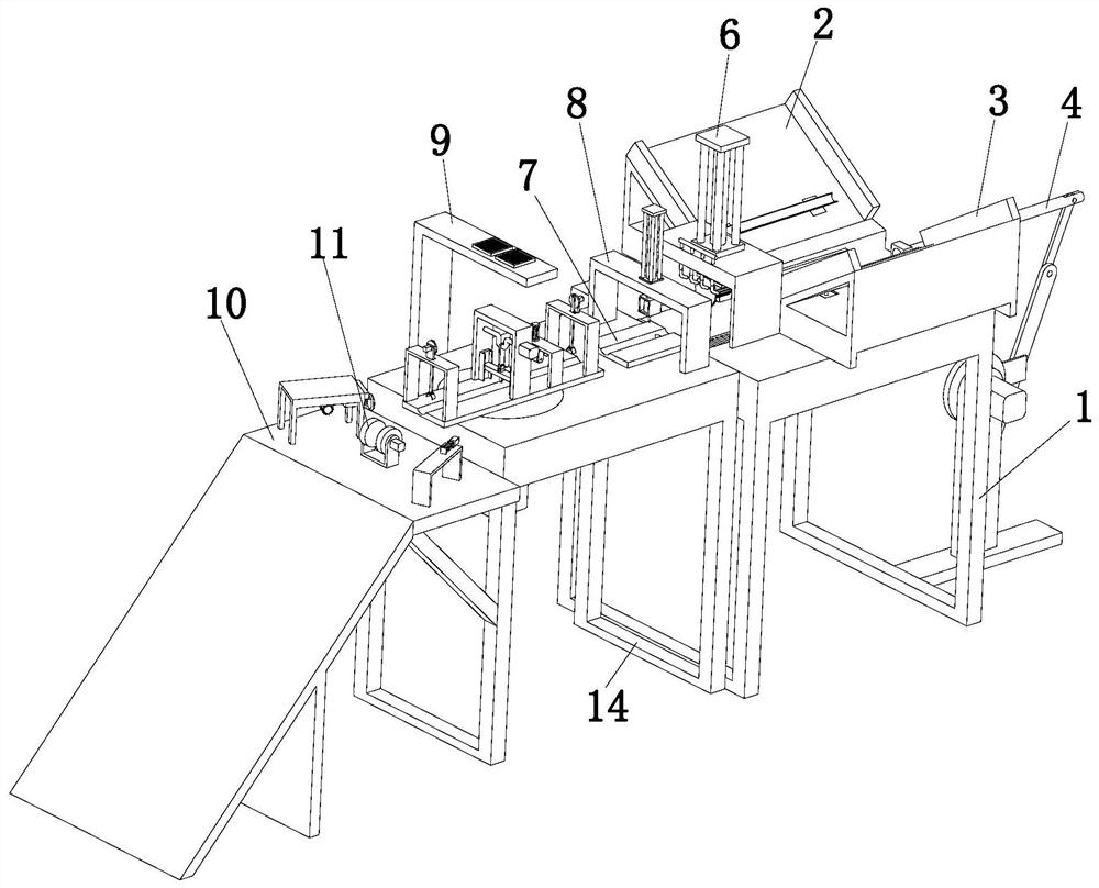
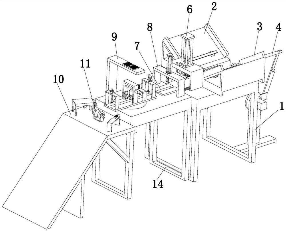
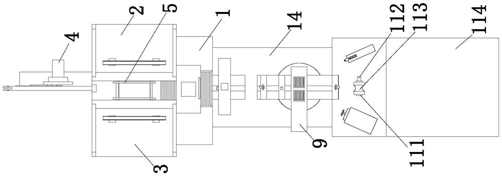
The invention discloses an automatic machining process for a fan stand column, and belongs to the technical field of fans. The automatic machining process comprises the following steps that 1, an inner pipe and an outer pipe of the fan stand column are automatically fed; 2, the inner pipe and the outer pipe of the fan stand column are conveyed to a fixing station; 3, the inner pipe and the outer pipe of the fan stand column are fixed; 4, the fan stand column is automatically cut; 5, the fan stand column is automatically punched; 6, the fan stand column is moved to a stand column shaping station; 7, the two ends of the inner pipe and the two ends of the outer pipe of the fan stand column are fixed; 8, double-buckle punching is conducted on the inner pipe and the outer pipe; 9, dust and waste residues are cleaned up after punching and stamping; 10, the two ends of the inner pipe are shaped; 11, the inner circle of the inner pipe is shaped; 12, the outer circle of the inner pipe is shaped; and 13, the inner pipe and the outer pipe are automatically discharged. The process is ingenious in design, smooth in procedure connection and high in automation degree, full-automatic production of the fan stand column is achieved, and remarkable economic value is achieved.

Description

technical field [0001] The invention relates to the technical field of fans, in particular to an automatic processing technology for a fan column. Background technique [0002] The column fan is a fan using a centrifugal fan. It adopts a cylindrical column shape and does not take up space when placed in the room; and the fan blades are wrapped in the casing, which is difficult to touch and relatively safe; and the sound is relatively small, Quiet and no noise. Because of these advantages, it has been widely used. The fan column is generally composed of a column outer tube and a column inner tube. In actual use, the inner tube of the column is sleeved in the inner tube of the column. In actual production, the column of the fan needs to be processed in various steps for subsequent use. [0003] However, when the existing fan column processing device processes the outer tube and the inner tube of the column, the outer tube and the inner tube of the column are processed manua...

Claims


Application Information

Patent Timeline
IPC IPC(8): B23P15/00B23Q5/28B23Q7/00B23Q11/00
CPCB23P15/00B23Q5/28B23Q7/00B23Q11/0042
Inventor 钟起官
Owner 钟起官
Why Eureka
Try Eureka