
Rotor punching sheet, rotor iron core, motor rotor, assembling method and motor

A technology of rotor punching and motor rotor, which is applied in the field of motor rotor and assembly method, rotor core, motor, and rotor punching, and can solve the problems of reducing the degree of magnetic flux leakage of the outer circle magnetic bridge of the rotor, complex production and assembly, etc.

Active Publication Date: 2021-05-18
GREE ELECTRIC APPLIANCES INC
View PDF7 Cites 2 Cited by
  • Summary
  • Abstract
  • Description
  • Claims
  • Application Information

AI Technical Summary

Problems solved by technology

[0004] In the prior art, the end of the magnetic steel groove away from the rotor axis is made to penetrate the outer circle of the rotor to reduce the degree of magnetic flux leakage at the magnetic isolation bridge of the outer circle of the rotor. The rotor yoke and the fixed yoke are assembled to realize the removal of the magnetic isolation bridge and the positioning of the permanent magnet, and the production and assembly are complicated

Method used


Image

  • Rotor punching sheet, rotor iron core, motor rotor, assembling method and motor
  • Rotor punching sheet, rotor iron core, motor rotor, assembling method and motor
  • Rotor punching sheet, rotor iron core, motor rotor, assembling method and motor

Examples


Embodiment Construction

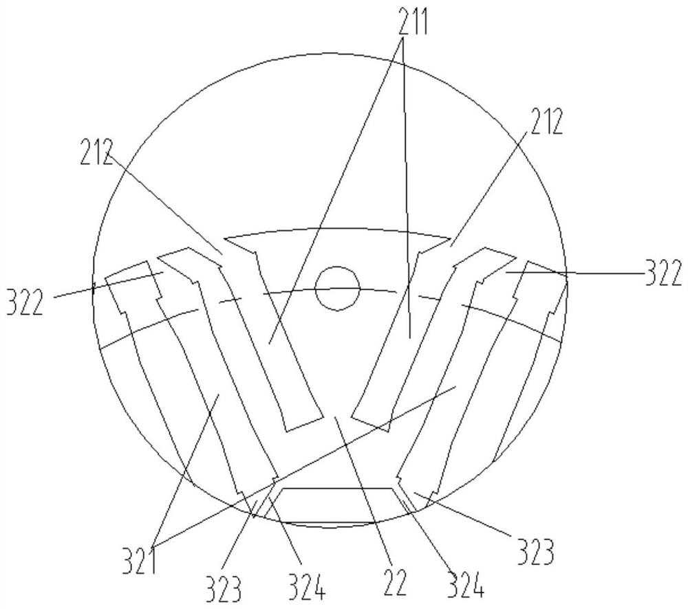
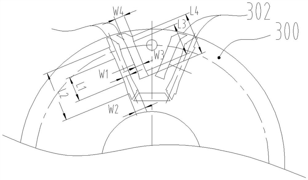
[0048] see in conjunction Figure 1 to Figure 11 As shown, according to the embodiment of the present invention, a rotor stamping is provided, which includes a stamping body 1, and the stamping body 1 has a plurality of magnetic pole forming regions corresponding to the motor rotor poles, and each magnetic pole forming region A first magnetic barrier groove 2 is configured on the punch body 1, and the first magnetic barrier groove 2 is symmetrical about the d-axis in the corresponding magnetic pole forming region and forms a first magnetic barrier groove facing the outer peripheral side of the punch body 1 Open angle structure, the bottom of the first magnetic barrier slot 2 has a first magnetic isolation bridge 22 on the d-axis, and the first magnetic barrier slot 2 includes two first sides symmetrical about the d-axis Extending magnetic barrier slot 21, the first laterally extending magnetic barrier slot 21 includes a first magnetic steel slot 211 and a first air slot 212 ra...


PUM


Abstract

The invention provides a rotor punching sheet, a rotor core, a motor rotor, an assembling method and a motor, the rotor punching sheet comprises a punching sheet body, the punching sheet body is provided with a plurality of magnetic pole forming areas corresponding to the magnetic poles of the motor rotor, and the punching sheet body in each magnetic pole forming area is provided with a first magnetic barrier groove; the first magnetic barrier grooves are symmetrical about the d axis in the corresponding magnetic pole forming area and form a first field angle structure facing the peripheral side of the punching sheet body, the bottom of each first magnetic barrier groove is provided with a first magnetic isolation bridge located on the d axis, and each first magnetic barrier groove comprises two first laterally-extending magnetic barrier grooves symmetrical about the d axis. each first laterally-extending magnetic barrier groove comprises a first magnetic steel groove and a first air groove located on the radial outer side of the first magnetic steel groove, and the first air groove is communicated with the peripheral wall of the punching sheet body. According to the invention, because the outer circle of the rotor punching sheet is not provided with a magnetic isolation bridge, the magnetic leakage at the magnetic isolation bridge can be reduced, the salient pole ratio of the rotor is improved, and the torque output capability of the motor is enhanced.

Description

technical field [0001] The invention belongs to the technical field of motor manufacturing, and in particular relates to a rotor punch, a rotor iron core, a motor rotor, an assembly method, and a motor. Background technique [0002] At present, asynchronous motor systems are mostly used in the field of electrical transmission. Compared with asynchronous motor systems, permanent magnet motor systems have the characteristics of low loss and high efficiency, which is the development trend of the next generation of transmission systems. Due to the high back electromotive force of ordinary permanent magnet synchronous motors, there is a danger of damaging the inverter during high-speed operation, so permanent magnet assisted synchronous reluctance motors are favored. The synchronous reluctance motor has high reliability, because there is no permanent magnet on the rotor, so there is no risk of loss of magnetism, but the low power factor is a major shortcoming of the synchronous r...

Claims


Application Information

Patent Timeline
IPC IPC(8): H02K1/22H02K1/27H02K1/28H02K21/02H02K15/03
CPCH02K1/22H02K1/27H02K1/28H02K21/028H02K15/03H02K2213/03
Inventor 黎永材童童廖克亮李世鹏张健王勇
Owner GREE ELECTRIC APPLIANCES INC
Learn More