Micro-grid harmonic suppression method based on synchronous inversion technology

A harmonic suppression and synchronous inverter technology, applied in AC network to reduce harmonic/ripple, harmonic reduction device, irreversible DC power input conversion to AC power output, etc., can solve a large number of harmonics in microgrid Waves, unsatisfaction, lack of inertia and damping for micro-sources

Pending Publication Date: 2021-05-18
STATE GRID LIAONING ECONOMIC TECHN INST +1
View PDF5 Cites 0 Cited by
  • Summary
  • Abstract
  • Description
  • Claims
  • Application Information

AI Technical Summary

Problems solved by technology

[0002] At present, the micro-grid control method is mainly to control the grid-side voltage and current of the micro-source in the micro-grid by controlling the inverter. Compared with the traditional power grid that mostly uses synchronous generators as power sources, the micro-source in the micro-grid lacks inertia. and damping, considering that a large number of distributed power sources are connected to the microgrid, it will have a negative impact on it to a certain extent
Moreover, when the microgrid operates in an island, since there is no support from the external grid, the internal fully-controlled power electronic inverter and the nonlinear load on the load side will cause a large number of harmonics in the microgrid, which will affect the voltage of the microgrid. The quality has a serious impact and cannot meet the needs of users with high requirements on power quality

Method used


Image

  • Micro-grid harmonic suppression method based on synchronous inversion technology
  • Micro-grid harmonic suppression method based on synchronous inversion technology
  • Micro-grid harmonic suppression method based on synchronous inversion technology

Examples


Embodiment Construction

[0069] The present invention will be described in further detail below in conjunction with the accompanying drawings.

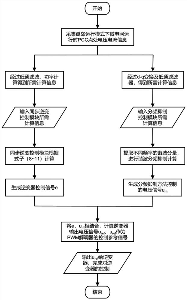
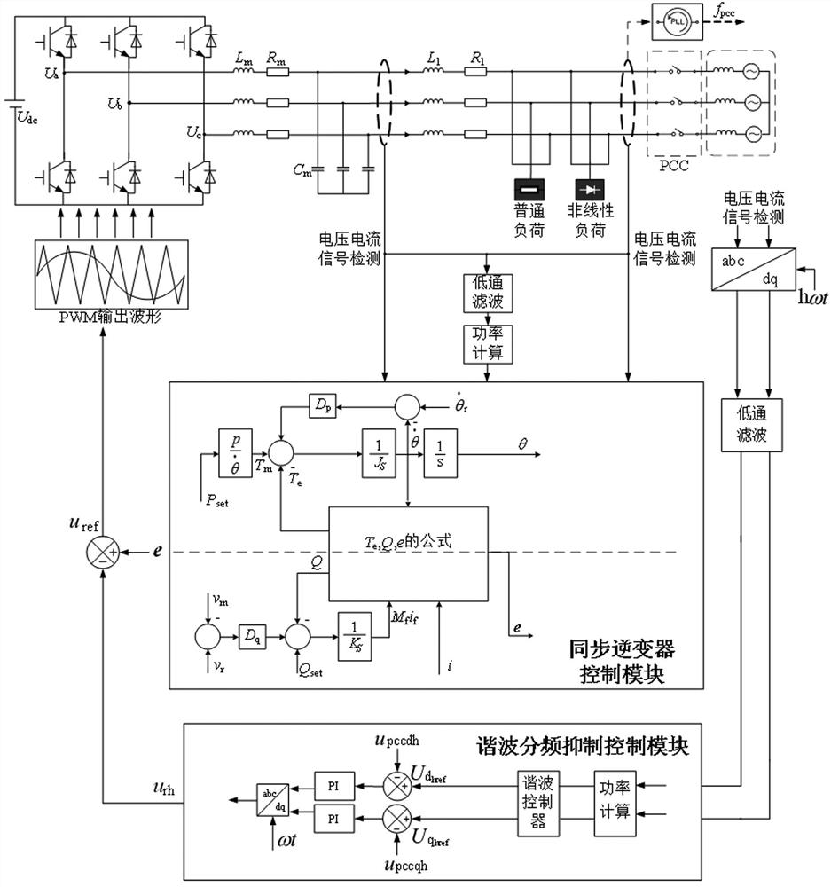
[0070] The specific flow of the invention is attached figure 1 As shown, the present invention proposes a microgrid harmonic suppression method based on synchronous inverter technology. The method is based on synchronous inverter technology control. When the microgrid is in the island operation mode, the microgrid operating time is collected from the PCC point According to the collected power information, the power and harmonic information required by each control module are calculated, and then sent to the synchronous inverter control module and the harmonic frequency division suppression control module for control. The signal processed by the synchronous inverter control method is combined with the voltage signal controlled by the frequency division suppression method, and the inverter control signal is generated after the double-loop control to control the...


PUM


Abstract

The invention discloses a micro-grid harmonic suppression method based on a synchronous inversion technology. Firstly, according to a voltage output model of a micro-source inverter in a micro-grid, a harmonic suppression method is researched by analyzing a harmonic generation reason and a voltage quality deterioration mechanism in the micro-grid in an isolated island operation state; secondly, according to the reason and mechanism of harmonic generation, the harmonic is suppressed by adopting a control strategy of combining a synchronous inverter and frequency division suppression, and the relationship between each system parameter of the synchronous inverter and active power P and reactive power Q is obtained by analyzing the mathematical model of the synchronous generator; a synchronous inverter control module with frequency and voltage control and active and reactive power regulation is designed; according to voltage information of a system, after d-q conversion and a low-pass filter, harmonic components of different frequencies of system voltage are extracted, and a harmonic frequency division suppression control module is designed based on a harmonic frequency division suppression algorithm.

Description

technical field [0001] The invention is suitable for harmonic suppression of micro-grid, is a harmonic suppression method based on synchronous inverter technology, and belongs to the technical field of inverter control. Background technique [0002] At present, the micro-grid control method is mainly to control the grid-side voltage and current of the micro-source in the micro-grid by controlling the inverter. Compared with the traditional power grid that mostly uses synchronous generators as power sources, the micro-source in the micro-grid lacks inertia. And damping, considering that a large number of distributed power sources are connected to the microgrid, it will have a negative impact on it to a certain extent. Moreover, when the microgrid operates in an island, since there is no support from the external grid, the internal fully-controlled power electronic inverter and the nonlinear load on the load side will cause a large number of harmonics in the microgrid, which w...

Claims


Application Information

Patent Timeline
IPC IPC(8): H02J3/01H02J3/38H02M7/48
CPCH02J3/01H02J3/388H02J3/381H02M7/48H02J2203/20H02J2300/40Y02E40/40
Inventor 高靖梅迪宋卓然佟俊达朱洪波杨博宋坤潘霄张娜王义贺程孟增商文颖李纯正满林坤刘禹彤杨朔董雁楠苑效宁颜宁马少华
Owner STATE GRID LIAONING ECONOMIC TECHN INST
Why Eureka
Try Eureka