Power battery top cover structure and power battery
A power battery and top cover technology, which is applied to small-sized batteries/battery packs, battery covers/end covers, batteries, etc., can solve the problems of complex processing, affecting product overcurrent capability or air leakage, and high cost
- Summary
- Abstract
- Description
- Claims
- Application Information
AI Technical Summary
Problems solved by technology
Method used
Image
Examples
Embodiment approach 1
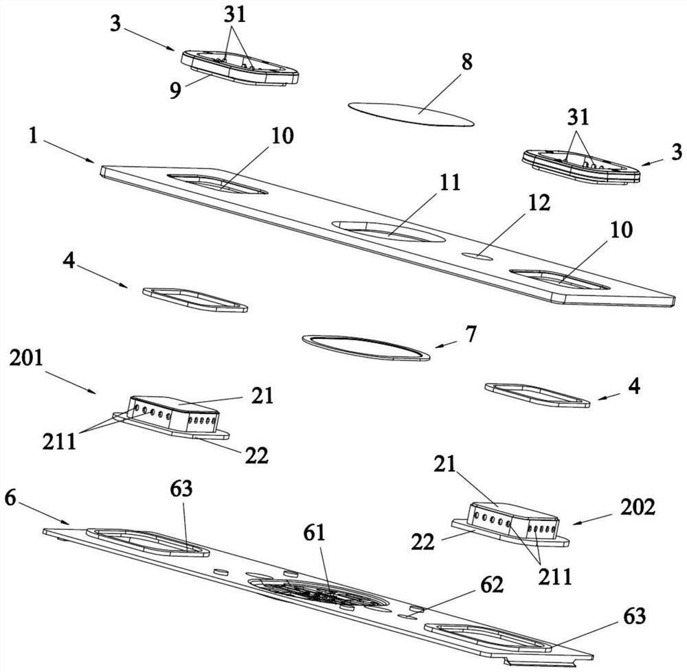
[0050] A power battery top cover structure, comprising a top cover sheet 1, provided with a pole through hole 10; a pole assembly, including an integrated pole 2, an upper plastic part 3 and a sealing ring 4, and the pole 2 penetrates the pole The through hole 10, the upper plastic part 3 is set between the side of the pole 2 and the top cover 1, the sealing ring 4 is set between the bottom of the pole 2 and the top cover 1; the outer wall of the pole 2 and the top cover 1 The inner wall of the upper plastic part 3 is concavo-convex, and is used to clamp the upper plastic part 3 to the pole 2 , and the outer edge 22 of the bottom of the pole 2 abuts against the bottom surface of the top cover 1 through the sealing ring 4 .
[0051] Because in the existing battery structure, the negative pole is composed of two base materials of copper and aluminum, through friction welding or composite plate, the processing is complicated and costly, and the contact surface of these two base ma...
Embodiment approach 2
[0065] The difference from the first embodiment is that the concave part of this embodiment includes a second concave part 212, the second concave part 212 is arranged around the outer wall of the cover body 21, and at least one reinforcing rib is provided at the junction between the bottom of the cover body 21 and the outer edge 22 5. An upward protrusion 221 is provided on the edge of the outer edge 22, and the protrusion 221 is arranged around the outer edge 22. The pole 2, the upper plastic part 3 and the sealing ring 4 are all circular, and the concave part is strip-shaped. Specifically, see Figure 7 and Figure 8 As shown, the second recess 212 is strip-shaped, and can be designed to be perpendicular to the top surface of the cover body 21, or can be designed to be parallel to the top surface of the cover body 21. The second recess 212 can be a continuous strip shape, or it can be a spacer A plurality of bar-shaped sections are set; the protrusion 221 can fix the posit...
Embodiment approach 3
[0068] The difference from Embodiment 1 is that the recesses in this embodiment include a first recess 211 and a second recess 212, the first recess 211 and the second recess 212 are arranged around the outer wall of the cover body 21, and the shape of the first recess 211 is the same as that of the second recess. The shape of the concave portion 212 is different, the pole 2, the upper plastic part 3 and the sealing ring 4 are all square or oval, and the concave portion is circular or strip-shaped. In this example, see Figure 9 to Figure 11 As shown, the first concave portion 211 is a circular blind hole, which can be evenly distributed on the four sides of the square cover body 21, and the number of the first concave portion 211 on each side is 5, which can be adjusted according to the actual sealing performance requirements. The number and spacing of the first recesses 211 are adjusted. At the same time, a strip-shaped second recess 212 is provided between adjacent first re...
PUM
| Property | Measurement | Unit |
|---|---|---|
| Thickness | aaaaa | aaaaa |
Abstract
Description
Claims
Application Information
 - R&D
- Intellectual Property
- Life Sciences
- Materials
- Tech Scout
- Unparalleled Data Quality
- Higher Quality Content
- 60% Fewer Hallucinations
Browse by: Latest US Patents, China's latest patents, Technical Efficacy Thesaurus, Application Domain, Technology Topic, Popular Technical Reports.
© 2025 PatSnap. All rights reserved.Legal|Privacy policy|Modern Slavery Act Transparency Statement|Sitemap|About US| Contact US: help@patsnap.com


