Eureka AIR delivers breakthrough ideas for toughest innovation challenges, trusted by R&D personnel around the world.

Anti-peeping display panel, anti-peeping display device, manufacturing method and using method

A display panel and display substrate technology, which is applied in semiconductor/solid-state device manufacturing, instrumentation, electrical digital data processing, etc., can solve problems such as narrowing of the light output angle, low practical feasibility and applicability, and inability to achieve flexible adjustment.

Pending Publication Date: 2021-05-18
BOE TECH GRP CO LTD
View PDF0 Cites 1 Cited by
  • Summary
  • Abstract
  • Description
  • Claims
  • Application Information

AI Technical Summary

Problems solved by technology

On the one hand, the existing anti-peeping displays need to narrow the light output angle through a relatively complex structure. On the other hand, most of them cannot be flexibly adjusted. Applicability is not high

Method used


Image

  • Anti-peeping display panel, anti-peeping display device, manufacturing method and using method
  • Anti-peeping display panel, anti-peeping display device, manufacturing method and using method
  • Anti-peeping display panel, anti-peeping display device, manufacturing method and using method

Examples


Embodiment Construction

[0058]In order to illustrate the present invention more clearly, the present invention will be further described below in conjunction with preferred embodiments and accompanying drawings. Similar parts in the figures are denoted by the same reference numerals. Those skilled in the art should understand that the content specifically described below is illustrative rather than restrictive, and should not limit the protection scope of the present invention.

[0059] It should be noted that "on", "formed on" and "arranged on" mentioned in this article may mean that one layer is directly formed or set on another layer, or that a A layer is indirectly formed or disposed on another layer, ie there are other layers between the two layers.

[0060] Based on one of the above problems, an embodiment of the present invention provides an anti-peep display panel, including a display substrate and an anti-peep device arranged on the light-emitting side of the display substrate, wherein:

...


PUM

PropertyMeasurementUnit
thicknessaaaaaaaaaa
thicknessaaaaaaaaaa
thicknessaaaaaaaaaa

Abstract

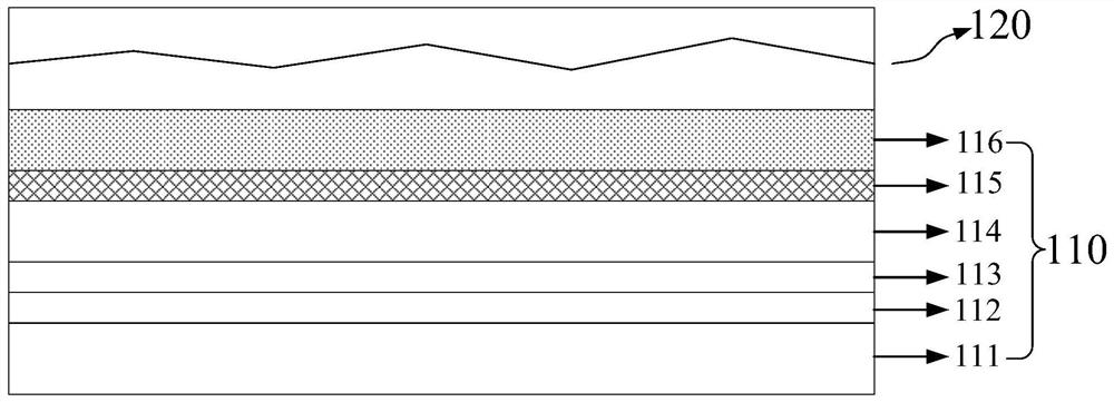
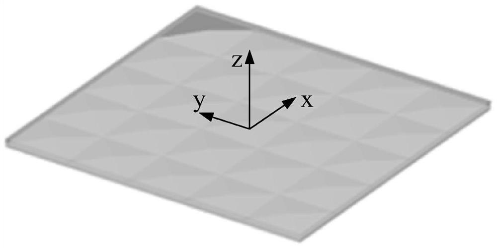
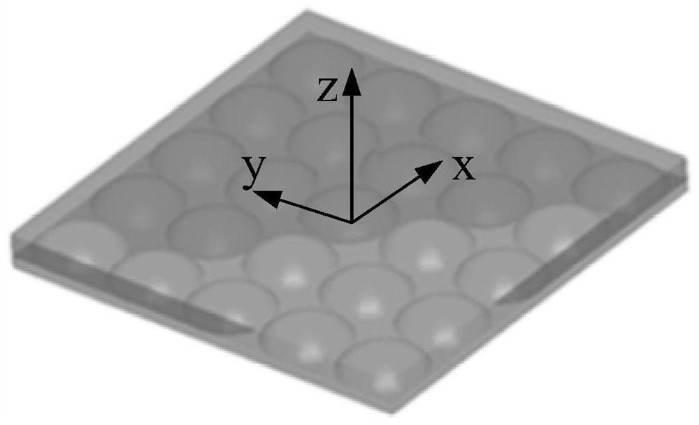
The invention discloses an anti-peeping display panel, an anti-peeping display device, a manufacturing method and a using method. The anti-peeping display panel comprises a display substrate and a peep-proof device arranged on the light-emitting side of the display substrate, the display substrate comprises a substrate body, a driving circuit layer, an anode, a light-emitting layer, a cathode with a first preset thickness and a light extraction layer with a second preset thickness, the driving circuit layer, the anode, the light-emitting layer, the cathode and the light extraction layer are sequentially stacked on the substrate body, and light emitted from the light extraction layer is quasi-collimation light; the peep-proof device comprises a first film layer with a fixed refractive index and a second film layer with a variable refractive index, the contact surface of the first film layer and the second film layer is of a non-planar structure, and the second film layer changes the refractive index in response to a loaded voltage so that the peep-proof device can directly emit or deflect and emit quasi-collimation light. According to the display panel provided by the embodiment of the invention, the display panel can be adjusted between peep-proof display and wide-viewing-angle display by limiting the thicknesses of the cathode and the light extraction layer and arranging the peep-proof device with the variable refractive index on the light emitting side of the display substrate.

Description

technical field [0001] The invention relates to the field of display technology, in particular to an anti-peep display panel, an anti-peep display device, a manufacturing method and a use method. Background technique [0002] The OLED display device is gradually becoming a mainstream device of a mainstream small and medium-sized display panel. This kind of OLED display device mostly uses an active matrix backplane, and the device structure is composed of a fully reflective anode, a semireflective and translucent cathode, and an organic film interposed therebetween. The fully reflective anode and the semi-reflective cathode together form a microcavity structure, which can enhance the brightness of the front surface of the device and improve the color purity of the front surface. [0003] Anti-peeping display is one of the special requirements of display panels, that is, for frontal observers, the panel display is normal, and for observers outside a certain angle (30°), the b...

Claims


Application Information

Patent Timeline
Patent Type & Authority Applications(China)
IPC IPC(8): H01L51/52H01L51/56H01L27/32G06F3/041G02F1/13
CPCG06F3/0412G02F1/1323H10K59/40H10K59/10H10K50/822H10K50/852H10K50/858H10K71/00
Inventor 李鑫石良瑜
Owner BOE TECH GRP CO LTD
Why Eureka
Eureka Blog
Learn More