


Quick Research
Generate reliable direction feasibility study reports for your R&D in just a few steps.

Technical Q&A
Discover and master advanced knowledge NOW. Basics, ideas, possibilities, all at once.

Find Solutions
As an expert in R&D theories, this can generate solutions to your technical problems instantly.

Evaluate Feasibility
Analyze your overall solution with one click, know your potential R&D risks in advance.

Monitor Landscape
Get weekly tech updates, stay abreast of the latest tech innovations and key insights.
Multifunctional sand table for urban planning, and using method thereof
A kind of urban planning and multi-functional technology, applied in the field of demonstration equipment, can solve the problem of inconvenient viewing of the sand table machine
- Summary
- Abstract
- Description
- Claims
- Application Information
AI Technical Summary
Problems solved by technology
Method used
Image


Examples
Embodiment 1
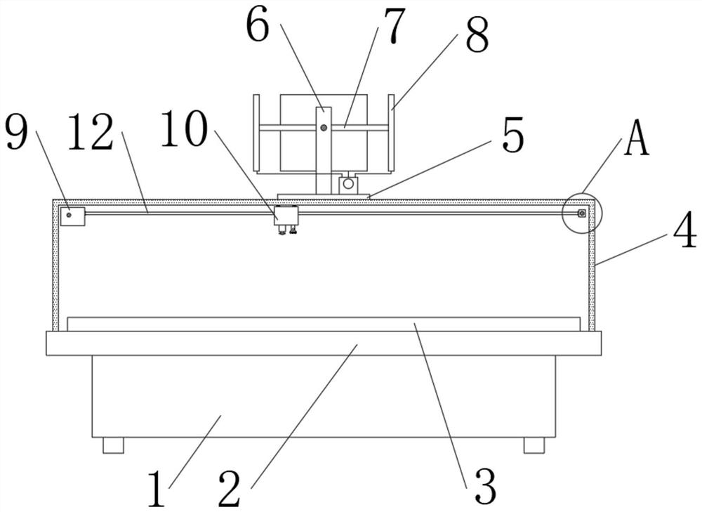
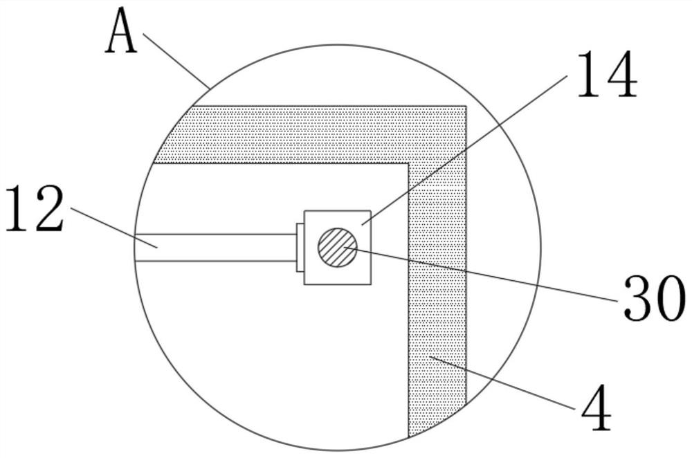
[0030] Such as Figure 1-6 As shown, the embodiment of the present invention provides a multifunctional sand table for urban planning, including a platform 2, a sand table 3 is fixedly connected in the middle of the top of the platform 2, and a dust-proof glass cover 4 is fixedly connected around the top of the platform 2, and the inside of the dust-proof glass cover 4 The top of one side is fixedly connected with a first threaded rod 11, and the top of the other side of the dustproof glass cover 4 is fixedly connected with a sliding rod 30. The first threaded rod 11 is provided with a first box 9, and the sliding rod 30 is slidably connected with a The slider 14, the second threaded rod 12 is fixedly connected between the first box body 9 and the slider 14, the second threaded rod 12 is provided with the second box body 10, and the bottom side of the second box body 10 is fixedly connected with a camera 24. The other side of the bottom of the second box body 10 is fixedly con...
Embodiment 2
[0037] An embodiment of the present invention provides a method for using a sand table for multifunctional urban planning, comprising the following steps:
[0038] S1. First, people can watch the sand table 3 used for urban planning through the dustproof glass cover 4. If there is an inconvenient viewing position, the first servo motor 17 can be started to rotate the first transmission gear 18 and drive the first driven gear 16. Rotate, and then make the first threaded tube 15 rotate, thereby make the first box body 9 move on the first threaded rod 11, can realize the longitudinal movement of the second box body 10;
[0039]S2. Then start the second servo motor 21 to rotate the second transmission gear 22 and drive the second driven gear 20 to rotate, and then the second threaded pipe 19 to rotate, so that the second box 10 moves on the second threaded rod 12 , the lateral movement of the second box body 10 can be realized;
[0040] S3. Through the vertical movement and later...
PUM
 Abstract
Description
Claims
Application Information
 - R&D Engineer
- R&D Manager
- IP Professional
- Industry Leading Data Capabilities
- Powerful AI technology
- Patent DNA Extraction
Browse by: Latest US Patents, China's latest patents, Technical Efficacy Thesaurus, Application Domain, Technology Topic, Popular Technical Reports.
© 2024 PatSnap. All rights reserved.Legal|Privacy policy|Modern Slavery Act Transparency Statement|Sitemap|About US| Contact US: help@patsnap.com