Laser direct etching metal cylindrical surface grating photoetching machine

A cylindrical grating and laser lithography technology, which is applied in the direction of diffraction grating, optomechanical equipment, micro-lithography exposure equipment, etc., can solve the problems of toxic production process, polluting environment, complex structure of lithography machine, etc.

Pending Publication Date: 2021-05-14
廊坊市莱格光电仪器有限公司
View PDF0 Cites 0 Cited by
  • Summary
  • Abstract
  • Description
  • Claims
  • Application Information

AI Technical Summary

Problems solved by technology

At present, the production technology of metal cylindrical gratings at home and abroad mainly has the following problems: First, the principle of domestic grating lithography technology is backward, and the technology is not directly engraved, but photoetched on the surface of the workpiece coated with a photosensitive film layer, and then It also needs to carry out processes such as development and corrosion, which has low work efficiency, no detection function, toxic production process and pollutes the environment, and generally only plane grating lithography can be carried out; It is complex and the manufacturing cost is very expensive. The lithography machine uses the high-precision XYZ three-coordinate motion principle to position the lithography, which is easy to generate additional errors in lithography, and the lithography machine has no detection function

Method used


Image

  • Laser direct etching metal cylindrical surface grating photoetching machine
  • Laser direct etching metal cylindrical surface grating photoetching machine
  • Laser direct etching metal cylindrical surface grating photoetching machine

Examples


Embodiment Construction

[0028] In order to enable those skilled in the art to better understand the technical solution of the present invention, the application will be described in detail below in conjunction with the accompanying drawings. The description in this part is only exemplary and explanatory, and should not have any limiting effect on the protection scope of the application. .

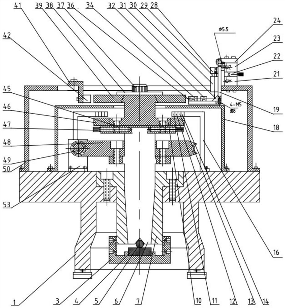
[0029] Such as figure 1 Shown is a schematic diagram of the first embodiment of the present application, including a base 1, a rotary system, a reference measurement and control circular grating system, a laser lithography system, and a control computing system;

[0030] The rotary system is arranged on the base 1; the reference measurement and control circular grating system includes a multi-code track reference circular grating 46 and a first reading module arranged above it; the multi-code track reference circular grating 46 is arranged on On the top of the rotary system, the top of the multi-code track refere...


PUM


Abstract

The invention provides a laser direct-etching metal cylindrical surface grating photoetching machine. The laser direct-etching metal cylindrical surface grating photoetching machine comprises a rotary system and a second grating reading head, wherein a multi-code-channel reference circular grating and a cylindrical grating base body are sequentially arranged at a top end of the rotary system from bottom to top, and the rotary system drives the multi-code-channel reference circular grating and the cylindrical grating base body to rotate; the laser photoetching system carries out photoetching on the cylindrical grating substrate; and the control calculation system is used for receiving a photoetching triggering reference signal and a detection reference signal sent by the multi-code-channel reference circular grating and a detected detection signal sent by the second grating reading head, sending a photoetching control signal to the laser photoetching system, and carrying out comparison calculation on the detection reference signal and the detected detection signal to obtain a detection result of photoetching precision. The machine is advantaged in that the rotary system drives the multi-code-channel reference circular grating and the cylindrical grating base body to synchronously rotate, the multi-code-channel reference circular grating can send out a photoetching triggering reference signal and a detection reference signal, and the photoetching machine also has a detection function besides a function of continuously photoetching the cylindrical grating base body.

Description

technical field [0001] The present disclosure relates to the technical field of metal cylinder grating lithography machine, in particular to a laser direct engraving metal cylinder grating lithography machine. Background technique [0002] Metal cylindrical grating is a modern high-precision and advanced optical reference element. It is widely used in the precise measurement and control of angular displacement because of its excellent characteristics such as high measurement and control precision, impact resistance, vibration, wide application, and convenient installation. , the lithography machine is the mother machine for manufacturing metal cylindrical gratings, which is related to the manufacturing level of metal cylindrical gratings. [0003] With the rapid development of modern science and technology, higher requirements such as high-precision manufacturing, high-efficiency manufacturing, and green environmental protection manufacturing have been put forward for the ma...

Claims


Application Information

Patent Timeline
Patent Type & Authority Applications(China)
IPC IPC(8): G02B5/18G03F7/00G03F7/20
CPCG02B5/1857G03F7/0005G03F7/20
Inventor 许殊罡史淑华许兴智李玉奎苏杰
Owner 廊坊市莱格光电仪器有限公司
Why Eureka
Try Eureka