Split type gap bridge structure of suspension body coal mining machine and body of ultra-thin coal seam coal mining machine

An extremely thin coal seam and shearer technology, applied in the field of shearer body and shearer bridge structure, can solve the problem of affecting production, the bridge structure cannot meet the supporting requirements of conveyors with different widths, and increase equipment maintenance costs, etc. question

Pending Publication Date: 2021-05-14
SHANGHAI TIANDI MINING EQUIP TECH CO LTD +2
View PDF0 Cites 0 Cited by
  • Summary
  • Abstract
  • Description
  • Claims
  • Application Information

AI Technical Summary

Problems solved by technology

The inner cavity of the bridge structure contains the function of the electric control box. Once the fixed connection of these two parts is damaged and fails, it will lead to the overall replacement of the electric control box, which affects production and increases equipment maintenance costs.
[0003] At the same time, the bridge structure of the same width cannot meet the matching requirements of conveyors of different widths. Therefore, when conveyors of different widths need to be matched, it is necessary to re-apply for safety standards and manufacturing, and the maintenance cost of equipment is greatly increased.

Method used


Image

  • Split type gap bridge structure of suspension body coal mining machine and body of ultra-thin coal seam coal mining machine
  • Split type gap bridge structure of suspension body coal mining machine and body of ultra-thin coal seam coal mining machine
  • Split type gap bridge structure of suspension body coal mining machine and body of ultra-thin coal seam coal mining machine

Examples


Embodiment Construction

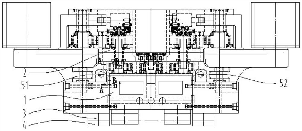
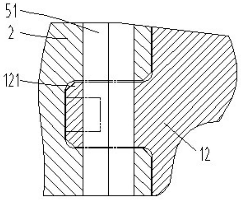
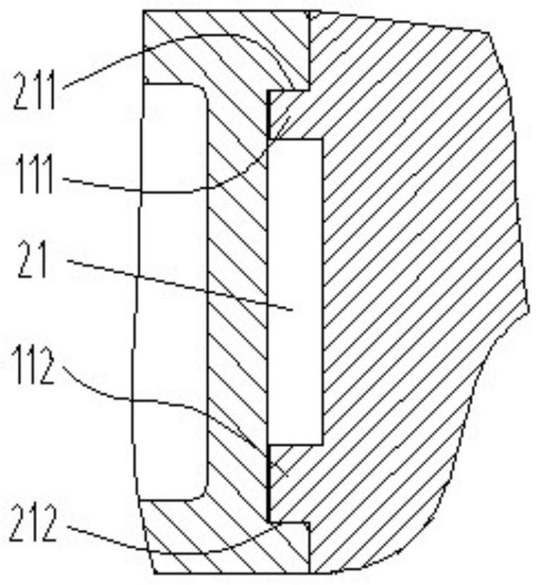
[0033] The invention discloses a split bridge structure 1 for a coal shearer with a suspended body, such as Figure 1-8 As shown, it includes a middle box body 11 and a left connecting block 12 and a right connecting block 13 respectively detachably fixed on the left and right sides of the middle box body, and the connection between the middle box body and the left connecting block and the right connecting block The positioning method can be through the vertical end faces that fit each other and one or more positioning pins that vertically pass through the two end faces that fit each other. The front end face of the middle box body is provided with an upper positioning boss 111 and a lower positioning boss 112 which are horizontally protruding and extend left and right. (For example, the left front part of the right connecting block) is respectively provided with a left connecting ear 121 and a right connecting ear 131 protruding horizontally forward, and the earholes on the l...


PUM


Abstract

The invention relates to a split type gap bridge structure of a suspension body coal mining machine and a body of an ultra-thin coal seam coal mining machine. The gap bridge structure comprises a middle box body, a left connecting block and a right connecting block which are connected with one another, wherein an upper positioning boss and a lower positioning boss are arranged on the front end surface of the middle box body; a left connecting lug and a right connecting lug are respectively arranged at the front parts of the left connecting block and the right connecting block; the body comprises a fixed reduction gearbox shell, a gap bridge structure, a front guide plate and a rear guide plate; the upper plane of the upper positioning boss and the lower plane of the lower positioning boss respectively form positioning matching surfaces with the upper groove wall and the lower groove wall of a positioning groove in the rear end surface of the fixed reduction gearbox shell; the left connecting lug and the right connecting lug are respectively inserted into a left groove and a right groove in the fixed reduction gearbox shell and are matched with a left positioning pin shaft hole and a right positioning pin shaft hole; the rear ends of the left connecting block and the right connecting block are respectively connected with a pair of front guide plate and rear guide plate; and guide groove structures with lower openings are formed in the paired front guide plate and rear guide plate. According to the split type gap bridge structure, a damaged part of a supporting part is replaced, and the split type gap bridge structure can be matched with conveyors with different widths.

Description

technical field [0001] The invention relates to a shearer bridge structure and a shearer fuselage with the bridge structure. The bridge structure is assembled from a plurality of parts arranged in left and right directions. Background technique [0002] For extremely thin coal seam shearers, in order to reduce the height of the machine surface and make full use of the side space of the coal wall, the main part other than the rocker arm is usually divided into two parts: the bridge structure and the fixed reduction box. The bridge structure spans above the conveyor. The fixed reduction box is arranged on the side of the coal wall of the conveyor. In order to avoid transportation difficulties caused by oversized dimensions, the bridge structure and the fixed reduction box are usually two structures that are detachably and fixedly connected. The inner cavity of the bridge structure contains the function of the electric control box. Once the fixed connection of these two parts ...

Claims


Application Information

Patent Timeline
IPC IPC(8): E21C35/00
CPCE21C35/00
Inventor 章立强周常飞王振乾胡璟刘昆民陶高群胡滔董超陈峤鹰宋振顾恩洋丁海春何利宁郭岱钱立全徐卫鹏王晓军林杭吕瑞林阚锦彪卢运鹏钱壮壮
Owner SHANGHAI TIANDI MINING EQUIP TECH CO LTD
Why Eureka
Try Eureka