Sewage treatment sludge drying furnace

A technology of sludge drying and sewage treatment, applied in the direction of dehydration/drying/concentrated sludge treatment, etc., can solve the problem that the fried material board cannot be fried and so on.

Active Publication Date: 2021-05-14
CHINA CONSTR THIRD BUREAU GREEN IND INVESTMENT CO LTD
View PDF6 Cites 0 Cited by
  • Summary
  • Abstract
  • Description
  • Claims
  • Application Information

AI Technical Summary

Problems solved by technology

[0006] At the same time, during the pyrolysis process, the material gradually dries and the humidity gradually decreases. The particle size of the dried sludge material gradually decreases during the rotation process, and the agglomeration gradually decreases. However, during the pyrolysis process, part of the material Failure to fully contact the pyrolysis gas causes the material to remain agglomerated. Most of the furnaces disclosed in the prior art use a stir-fry board in the furnace, but the stir-fry board can only stir-fry the material. For small agglomerated materials, the stir-fry The board doesn't fry it enough

Method used


Image

  • Sewage treatment sludge drying furnace
  • Sewage treatment sludge drying furnace
  • Sewage treatment sludge drying furnace

Examples


Embodiment 1

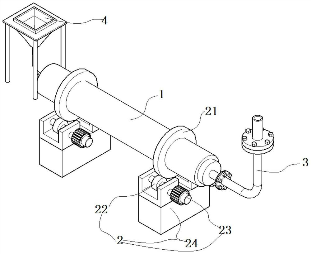
[0058] Such as Figure 1-9 As shown, a sewage treatment sludge drying furnace includes a drying furnace body, and the drying furnace body includes an outer furnace cylinder 1 and a trumpet-shaped inner furnace cylinder 5 assembled in the outer furnace cylinder 1 .

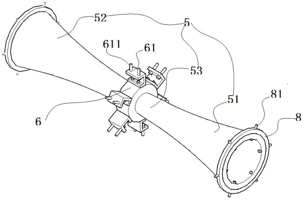
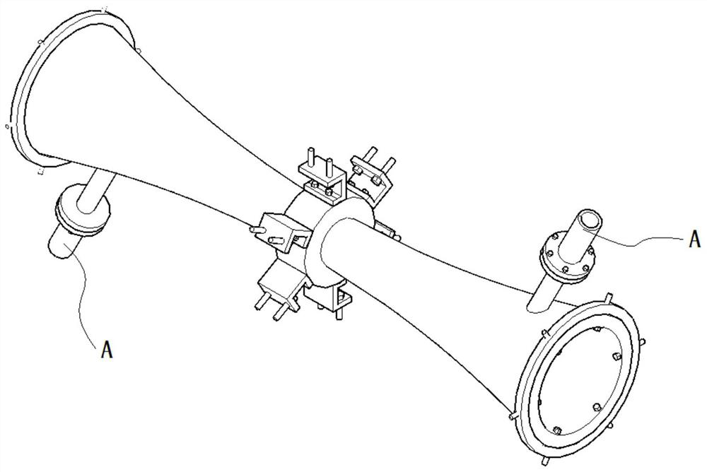
[0059] One of the improvement points of the present invention is to design the traditional cylindrical inner furnace drum into a trumpet-shaped inner furnace drum 5 .

[0060]Specifically, the shape of the trumpet-shaped inner furnace tube 5 includes a left tapered portion 52 and a right tapered portion 51 , and the left tapered portion 52 and the right tapered portion 51 . There is an intermediate portion 53 between the left tapered portion 52 and the right tapered portion 51 .

[0061] The radial lengths of the longitudinal cross-sectional shapes from the left tapered portion 52 to the middle portion 53 and from the middle portion 53 to the right tapered portion 51 decrease successively from large to small, whil...

Embodiment 2

[0088] Embodiment 2 pyrolysis efficiency comparative test

[0089] Such as Figure 10 As shown, the device disclosed in Example 1 of the present invention and the conventional drying furnace disclosed in the prior art are used to process the sludge produced by the same batch of sewage for drying operation. The processing pyrolysis efficiency curve of the present invention is as L1, and the existing The conventional drying furnace pyrolysis efficiency curve disclosed in the technology is L2.

[0090] From the data graphs of L1 and L2 processing, it can be seen that the device disclosed in the present invention has better efficiency in processing dried sludge. Among them, pyrolysis efficiency=qualified material / total amount of material, wherein, the qualified material is obtained through sieving, and is confirmed as a qualified product through physical and chemical characteristic testing.


PUM


Abstract

The invention discloses a sewage treatment sludge drying furnace which comprises a drying furnace body. The drying furnace body comprises an outer furnace barrel and a trumpet-shaped inner furnace barrel assembled in the outer furnace barrel. The trumpet-shaped inner furnace barrel comprises a left conical part and a right conical part. A middle part is arranged between the left conical part and the right conical part, and a mounting piece is assembled on the middle part. The mounting piece comprises a fixed disc sleeve fixedly connected to the middle part, a plurality of U-shaped mounting seats are fixedly connected to the disc outline of the fixed disc sleeve, and the U-shaped mounting seats are assembled on the outer furnace barrel through a plurality of assembly bolts in a threaded mode. The device further comprises a plurality of flow guide components assembled in the trumpet-shaped inner furnace barrel. Each flow guide component comprises a fixed ring body rod, and a plurality of annularly distributed leaf-shaped flow guide sheets are fixedly connected to each fixed ring body rod. A material grinding component is fixedly connected into the trumpet-shaped inner furnace barrel, and the drying furnace body is communicated with a pyrolysis gas inlet component. By adopting the device component design, the pyrolysis processing efficiency of materials is effectively improved.

Description

technical field [0001] The invention relates to the field of sewage treatment devices, in particular to a sludge drying furnace for sewage treatment. Background technique [0002] Sewage is the wastewater produced in the process of industrial production and agricultural production. Wastewater contains a large amount of organic matter, microorganisms and other polluting substances. Therefore, sewage needs to be recycled before it can be recycled. In the sewage treatment process, the sewage needs to be flocculated, settled and other operations, and the settled sludge waste can be processed into industrial materials such as activated carbon through pyrolysis and carbonization. [0003] In the pyrolysis process of sludge processing, the sludge material needs to be fed into the pyrolysis gas into the rotary furnace for pyrolysis, and the dried sludge is formed through the pyrolysis process, and the activated carbon is processed through the subsequent carbonization operation of th...

Claims


Application Information

Patent Timeline
IPC IPC(8): C02F11/12
CPCC02F11/12
Inventor 贾代玉
Owner CHINA CONSTR THIRD BUREAU GREEN IND INVESTMENT CO LTD
Why Eureka
Try Eureka