
Electromagnetic simulation method based on compression type finite element tearing butt joint method

An electromagnetic simulation and finite element technology, applied in design optimization/simulation, image data processing, special data processing applications, etc., can solve problems such as large memory consumption and low calculation efficiency, and achieve low memory consumption, improved solution efficiency, and computing The result is precise effect

Inactive Publication Date: 2021-05-11
NANJING UNIV OF POSTS & TELECOMM
View PDF1 Cites 3 Cited by
  • Summary
  • Abstract
  • Description
  • Claims
  • Application Information

AI Technical Summary

Problems solved by technology

[0003] The finite element tearing butt joint method is to solve the calculation model in partitions and realize the regional coupling by introducing transmission conditions and Lagrangian multipliers. Although the solution efficiency is high, the process of solving the Lagrangian multipliers will involve Matrix-vector multiplication to the numerical Green's function. The numerical Green's function is usually a full array of dual unknowns on the adjoining surface of two regions. When the model is more complex, the number of unknowns will be extremely large. The matrix of the high-order full array -Vector multiplication will lead to low calculation efficiency and huge memory consumption, which is also contrary to the original intention of introducing the finite element tearing butt joint method to reduce the memory requirements for solving complex models and improve the solution efficiency

Method used


Image

  • Electromagnetic simulation method based on compression type finite element tearing butt joint method
  • Electromagnetic simulation method based on compression type finite element tearing butt joint method
  • Electromagnetic simulation method based on compression type finite element tearing butt joint method

Examples


Embodiment Construction

[0025] The technical solutions of the present invention will be further described below in conjunction with the accompanying drawings and embodiments.

[0026] Such as figure 1 The main flow of the electromagnetic simulation method based on the compression-type finite element tearing butt joint method described in the present invention is shown, including the following steps:

[0027] Step 1: Carry out 3D modeling of the simulation model, tear the original simulation model into a series of non-overlapping sub-domains, and discretize the grid of each sub-domain, introduce the Robin transmission condition and pull Grangian multipliers are used to realize the connection between subdomains; the specific process includes:

[0028] In order to solve the subdomain coupling problem, the Robin transmission condition and the Lagrangian multiplier are introduced in the subdomain i to be obtained. The electric field Lagrange multiplier is an unknown quantity of the electric field boundar...


PUM


Abstract

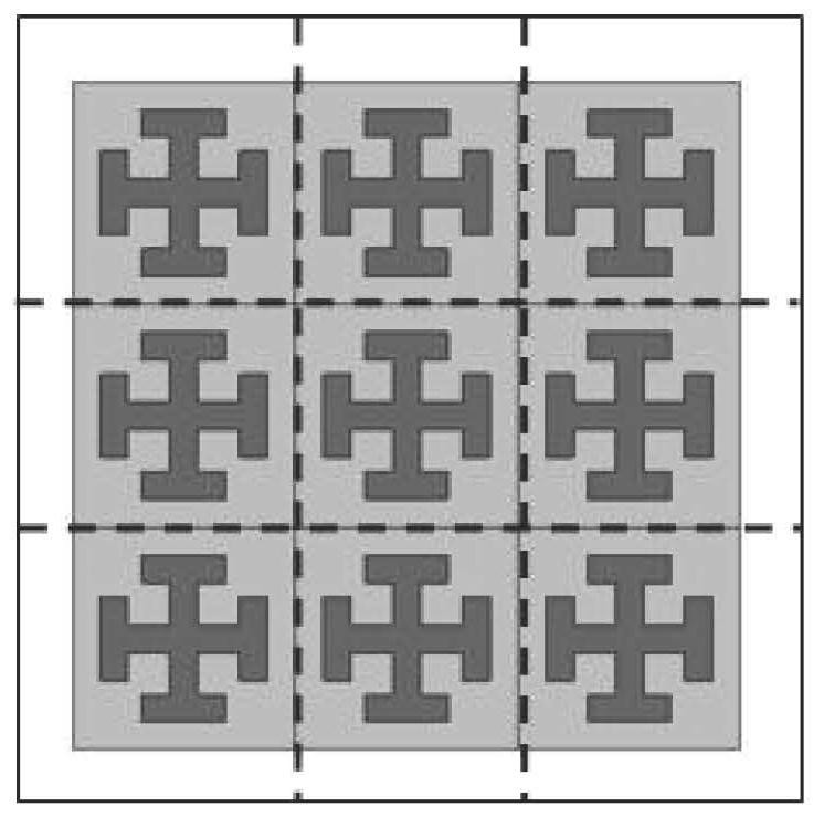
The invention discloses an electromagnetic simulation method based on a compression type finite element tearing butt joint method, which comprises the following steps: firstly, tearing a simulation model into a series of non-overlapping sub-domains; then, introducing a transmission condition into a sub-domain interface, building a sub-domain finite element equation and a global interface Lagrange multiplier equation, and compressing a numerical green function matrix involved in the sub-domain finite element equation and the global interface Lagrange multiplier equation in sequence through an adaptive crossover approximation algorithm and a singular value compression algorithm; and finally solving a Lagrangian multiplier and substituting the Lagrangian multiplier back into the sub-domain finite element equation to obtain global electric field distribution. Compared with a traditional finite element tearing butt joint method, the invention has higher solving efficiency and lower memory consumption. For a finite periodic structure, the compression process only needs to be carried out on several representative sub-domains, so that the invention has more obvious advantages compared with a traditional finite element tearing docking method.

Description

technical field [0001] The invention relates to an electromagnetic simulation method, in particular to an electromagnetic simulation method based on a compressed finite element tearing butt joint method. Background technique [0002] With the development of science and technology, especially the gradual improvement of computer technology, the expansion of memory and the improvement of computing power, the rapid development of computational electromagnetics has been promoted. Traditional computational electromagnetics problems can be independently analyzed on a single computer. But because of this, the actual engineering requirements are getting higher and higher, and the problems are becoming more and more complex. Even if some models can be analyzed on a single computer, the time and memory consumption required are huge, and many models require multiple computers. Computer joint solution, finite element tearing butt joint method is a method that can satisfy distributed and ...

Claims


Application Information

Patent Timeline
IPC IPC(8): G06F30/23G06T17/20G06T17/00
CPCG06T17/005G06T17/20G06F30/23
Inventor 宛汀张睿尧
Owner NANJING UNIV OF POSTS & TELECOMM
Learn More