Cotton suction branch pipe of spinning frame

A spinning frame and branch pipe technology, applied in textiles and papermaking, etc., can solve the problems of affecting the air conveying efficiency, large negative pressure loss, irregular air turbulence, etc., to improve the connection method, reduce negative pressure loss, and eliminate airflow disturbance. Effect

Inactive Publication Date: 2021-05-11
倪远
View PDF0 Cites 0 Cited by
  • Summary
  • Abstract
  • Description
  • Claims
  • Application Information

AI Technical Summary

Problems solved by technology

[0003] The branch pipe of the first form is directly connected to the main suction duct at an angle of 90 degrees, and the airflow entering the main suction duct forms a 90-degree angle with the airflow in the main suction duct, so that the number of spindles in the main suction duct is the same as the number of spinning frame spindles. The same 90-degree disturbed airflow makes the airflow in the main suction duct produce irregular turbulent flow, which affects the airflow delivery efficiency
[0004] The branch pipe of the second form is also connected to the main suction duct at an angle of 90 degrees, and the airflow entering the main suction duct forms a 90-degree angle with the airflow in the main suction duct, so that the number of knuckles in the main suction duct is the same as that of the spinning frame roller. The same 90-degree disturbed air flow, although the number of branch pipes is less than that of the first form, the air flow of each branch pipe is large, and the total disturbed air flow is similar to the first form, which makes the air flow in the main suction duct produce irregular turbulence , affecting the airflow delivery efficiency
Therefore, the air flow flows from the flute nozzle of each spindle position to the main suction duct, making three 90-degree turns in total, forming three turbulent flow disturbances, which greatly reduces the air transmission efficiency of the suction system, and the negative pressure loss is large

Method used


Image

  • Cotton suction branch pipe of spinning frame
  • Cotton suction branch pipe of spinning frame
  • Cotton suction branch pipe of spinning frame

Examples


Embodiment Construction

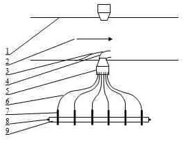
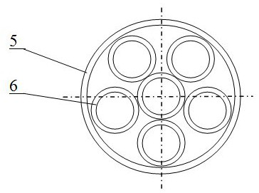
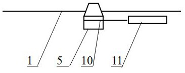
[0019] Refer to attached figure 1 and figure 2 , a cotton suction branch pipe of spinning frame, including branch pipe connection distributor 5 connected with main suction duct 1, branch pipe 6, branch nozzle 7 and branch pipe support rod 9. The interface with the main suction duct 1 and the branch pipe is a branch pipe connecting distributor 5 for multiple spindle positions. One end of the branch pipe 6 corresponding to each spindle position is inserted into the connection distributor 5, and the other end is connected to the branch nozzle of the corresponding spindle position. 7. The branch nozzle 7 is detachably clamped on the branch support rod 9, and the chucks 8 at both ends of the branch support rod 9 are detachably clamped on the roller seats on both sides, and the branch nozzle 7 is located at the output of the front roller jaw.

[0020] The branch pipe connection distributor 5 is one divided into four to ten spindle positions, especially one divided into four or fiv...


PUM


Abstract

The invention provides a cotton suction branch pipe of a spinning frame. According to the technical scheme of the cotton suction branch pipe of the spinning frame, a plastic round pipe with a smooth inner wall is adopted as the branch pipe, a connecting method of the branch pipe, a branch pipe nozzle and a main air suction pipe is improved, air resistance is reduced, 90-degree airflow disturbance of the branch pipe and the main air suction pipe are eliminated from multiple aspects, the whole branch pipe and connecting points thereof have no cotton accumulating and hanging positions, the airflow transmission efficiency of a cotton suction system is improved, the negative pressure loss is reduced, the maintenance performance is improved, and the device is suitable for new machine application and transformation of stock spinning frames.

Description

technical field [0001] The invention relates to the field of spinning equipment, and relates to a cotton suction pipe of a ring spinning machine, in particular to a cotton suction branch pipe connected from a main suction air pipe to an output portion of the front roller jaws of each spindle position. Background technique [0002] The suction pipes of the ring spinning frame in the prior art are connected from the main suction pipe to the branch pipes at the output parts of the front roller jaws of each spinning position. A connecting hole is set at each corresponding spindle position on the pipeline, and a branch pipe for each spindle is connected to the output of the front roller jaw; the second is the short carriage of the spinning frame that occupies most of the spindles, and is connected with each roller on the main suction duct. A connection hole is opened in the corresponding middle part, and a branch pipe of each roller is connected to the flute tube. The flute tube ...

Claims


Application Information

Patent Timeline
Patent Type & Authority Applications(China)
IPC IPC(8): D01H11/00
CPCD01H11/005
Inventor 倪远
Owner 倪远
Why Eureka
Try Eureka