
Intelligent quenching equipment for cast iron

A kind of quenching equipment, intelligent technology, applied in the direction of quenching equipment, heat treatment equipment, improving energy efficiency, etc., to achieve the effect of easy processing

Pending Publication Date: 2021-05-11
王修涛
View PDF9 Cites 1 Cited by
  • Summary
  • Abstract
  • Description
  • Claims
  • Application Information

AI Technical Summary

Problems solved by technology

[0004] In order to overcome the shortcomings of the existing technology that the cooled iron blocks need to be manually removed with tools and the coolant needs to be added frequently manually, the technical problem to be solved is: to provide a cooling solution that can keep the coolant level stable and can automatically remove the coolant. Intelligent quenching equipment for cast iron that loosens the quenched iron block and can air-dry the iron block

Method used


Image

  • Intelligent quenching equipment for cast iron
  • Intelligent quenching equipment for cast iron
  • Intelligent quenching equipment for cast iron

Examples


Embodiment 1

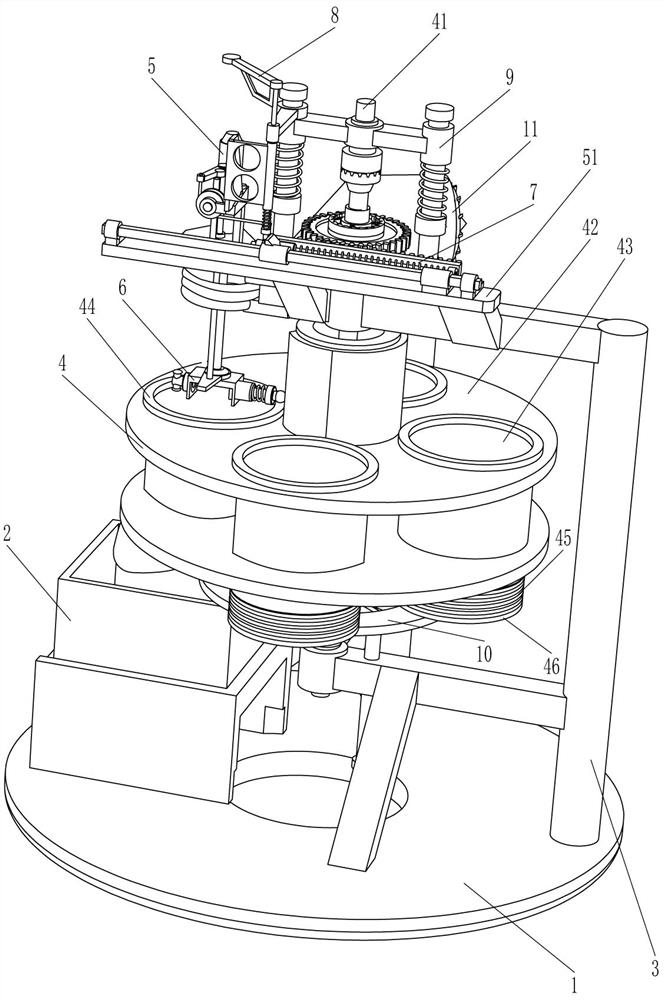
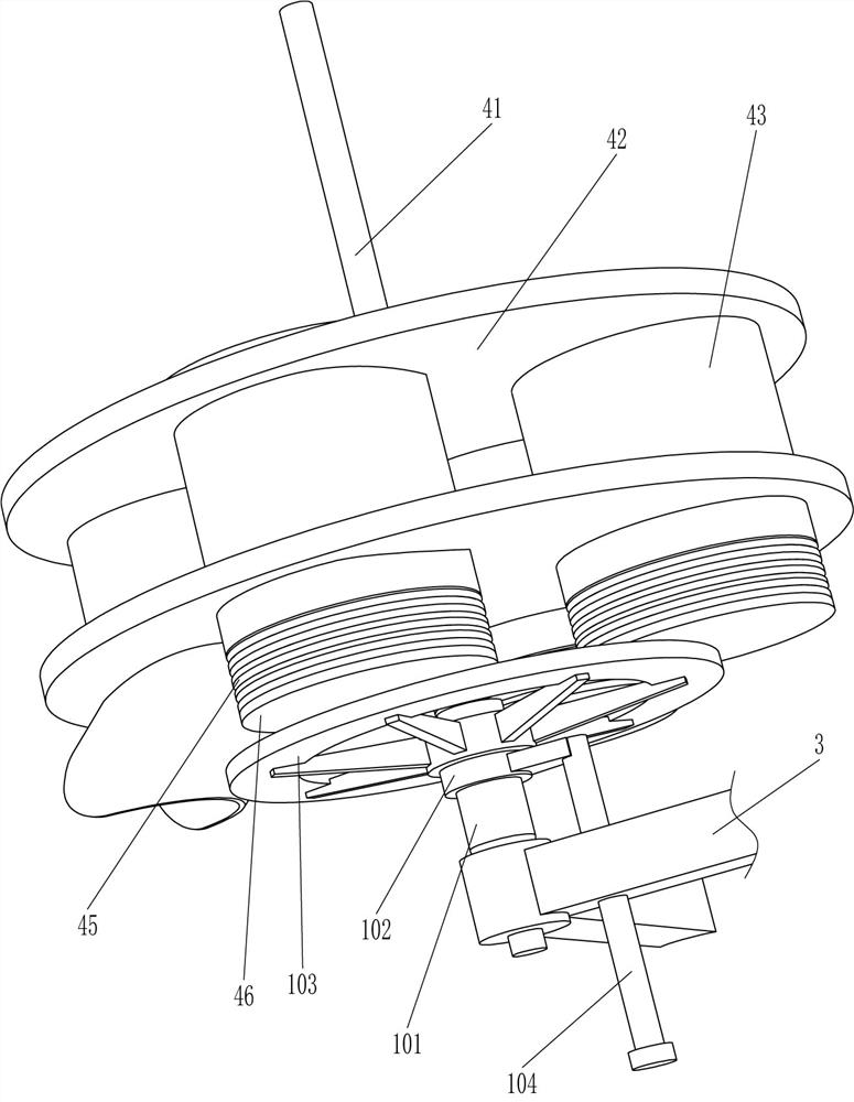
[0029] An intelligent quenching equipment for cast iron, such as figure 1 , figure 2 , image 3 , Figure 4 and Image 6 As shown, it includes a base 1, a collection frame 2, a mounting frame 3, a replacement mechanism 4, a lifting mechanism 5, a clamping mechanism 6, and a driving mechanism 7. The collection frame 2 is placed on the left side of the base 1, and the mounting frame is provided on the base 1. 3. The installation frame 3 is provided with a replacement mechanism 4 in a rotating manner, the installation frame 3 is provided with a lifting mechanism 5, the lifting mechanism 5 is provided with a clamping mechanism 6, and the lifting mechanism 5 is provided with a driving mechanism 7.

[0030] When people need to use this equipment, first people loosen the clamping mechanism 6, and place the iron block between the clamping mechanisms 6, then make the clamping mechanism 6 clamp the iron block, and at the same time, people enter the replacement mechanism 4 Add diffe...

Embodiment 2

[0037] On the basis of Example 1, such as figure 1 , figure 2 , Figure 4 , Figure 5 , Image 6 and Figure 7 As shown, it also includes a locking mechanism 8. The locking mechanism 8 includes a wedge block 81, a guide tube 82, a locking lever 83, a third spring 84 and a contact frame 85. A wedge is provided between the first sliding sleeve 77 and the square hole sleeve 75. Block 81, special-shaped frame 55 is provided with guide tube 82, and guide tube 82 slide type is provided with locking bar 83, and locking bar 83 cooperates with wedge block 81, is provided with the 3rd spring 84 between locking bar 83 and guide tube 82, A contact frame 85 is arranged on the locking rod 83 , and the contact frame 85 cooperates with the driving rod 71 .

[0038] In the initial state, the locking rod 83 blocks the wedge block 81, so that when the driving rod 71 moves upwards, the pull cord 72 pulls the first sliding rod 78 to move to the left, and the second spring 79 is compressed, b...


PUM


Abstract

The invention relates to quenching equipment, in particular to intelligent quenching equipment for cast iron. According to the intelligent quenching equipment for the cast iron, the liquid level of cooling liquid can be kept stable, quenched iron blocks can be automatically loosened, and the iron blocks can be air-dried. The intelligent quenching equipment for the cast iron comprises a base, a mounting plate, a replacement mechanism, a lifting mechanism and a clamping mechanism. A collecting frame is placed on the base. The mounting frame is arranged on the base. The replacement mechanism is rotationally arranged on the mounting frame. The lifting mechanism is arranged on the mounting frame. The clamping mechanism is arranged on the lifting mechanism. According to the intelligent quenching equipment for the cast iron, the iron blocks of different sizes are clamped through the clamping mechanism, then cooling liquid is contained through the replacing mechanism, then the iron blocks move up and down and the replacing mechanism intermittently rotates under the cooperation of the lifting mechanism and the driving mechanism, people can conveniently conduct quenching machining on the iron blocks, and the collecting frame can be used for collecting the quenched iron blocks.

Description

technical field [0001] The invention relates to a quenching device, in particular to an intelligent quenching device for cast iron. Background technique [0002] After the iron block is quenched, its performance will be more stable. When workers quench the iron block, they usually need to immerse the iron block in different coolants for quenching. At present, most of the iron blocks are manually quenched. Workers need to use tongs Clamp the red-hot iron block, then immerse the iron block in the cooling liquid, then take out the iron block, then heat the iron block red, and then immerse the iron block in the cooling liquid again, after repeated several times, the quenching is completed , wherein due to the high temperature of the iron block, manual quenching is easy to be scalded, and the existing quenching device usually requires manual use of tools to remove the cooled iron block, and because the cooling liquid is consumed quickly, so in order to maintain The stability of ...

Claims


Application Information

Patent Timeline
IPC IPC(8): C21D1/63C21D1/10
CPCC21D1/63C21D1/10Y02P10/25
Inventor 王修涛
Owner 王修涛
Learn More