Hardware cast iron die-casting stamping die

A stamping die and cast iron technology, which is applied in the field of metal cast iron die-casting stamping dies, can solve problems such as the reduction of die precision and service life, the increase of die and workpiece damage rate, and the drop of workpieces, so as to improve the accuracy and service life and improve production The effect of improving work efficiency and improving product qualification rate

Active Publication Date: 2021-05-11
广州市科雄精密机械有限公司
View PDF9 Cites 0 Cited by
  • Summary
  • Abstract
  • Description
  • Claims
  • Application Information

AI Technical Summary

Problems solved by technology

[0004] In order to make up for the deficiencies of the existing technology, when the ejector mechanism in the upper mold ejects the workpiece downward, the workpiece is prone to drop accidents and collides with the lower mold, resulting in an increase in the damage rate of the mold and the workpiece, resulting in mold accuracy and The service life is reduced, and before the stamping die is used, it is often necessary to apply lubricating oil to the parts of the stamping die, so that the surface of the workpiece after stamping and forming is accompanied by sundries such as lubricating oil and wear debris, which need to be treated before it can be used. A problem proposed by the present invention Metal Cast Iron Die Casting Stamping Die

Method used


Image

  • Hardware cast iron die-casting stamping die
  • Hardware cast iron die-casting stamping die
  • Hardware cast iron die-casting stamping die

Examples


Embodiment approach

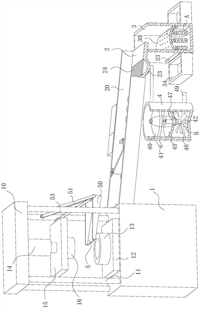
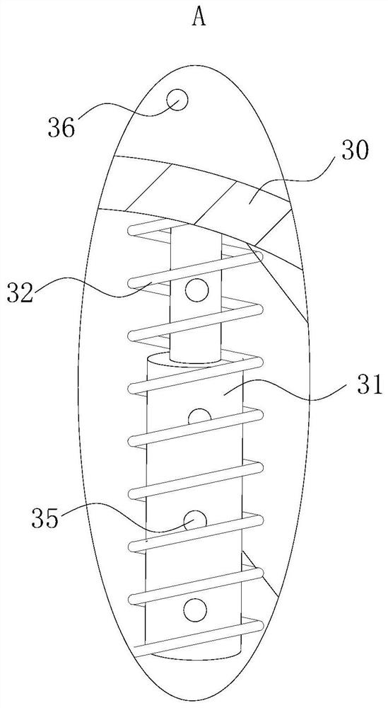
[0028] As an embodiment of the present invention, the first collection box 3 is slidably connected with a slide plate 30 with an arc-shaped cross-section. Arranged telescopic rod 31; the outside of the telescopic rod 31 is equipped with a third spring 32, and the two ends of the third spring 32 are fixedly connected with the lower surface of the slide plate 30 and the bottom inner wall of the first collection box 3; the first The left and right side walls of the collection box 3 are provided with a through groove 33 at the position below the slide plate 30, and the left and right sides of the first collection box 3 are provided with a second collection box 34, and the second collection box 34 is connected to the through groove. 33 one-to-one correspondence settings;

[0029] When working, the workpiece falls from the feeding plate 2 to the upper surface of the slide plate 30. When the workpiece falls, the impact and extrusion slide plate 30 moves downward continuously, so that...


PUM


Abstract

The invention belongs to the technical field of stamping dies, and particularly relates to a hardware cast iron die-casting stamping die. The hardware cast iron die-casting stamping die comprises a workbench, a feeding plate, a first collecting box and a liquid collecting barrel, wherein a material receiving plate is arranged at the position, between an upper die and a lower die, of one side of the workbench, and baffles are arranged on the front side and the rear side of the material receiving plate; first connecting rods are fixedly connected to the upper ends of the outer surfaces of the sides, away from the workbench, of the baffles, included angles between the first connecting rods and the upper surface of the material receiving plate are acute angles, and the ends, away from the material receiving plate, of the first connecting rods are rotationally connected with corresponding stand columns through rotating shafts; and a fixing rod is fixedly connected between the upper ends of the sides, away from the workbench, of the two baffles, and a second connecting rod is hinged between the middle of the fixing rod and an upper die fixing plate. According to the hardware cast iron die-casting stamping die, a workpiece can be prevented from colliding with the lower die, the precision of the die is improved, the service life of the die is prolonged, integration of demolding, material receiving and cleaning of the workpiece is realized, the operation time is saved, and the production working efficiency of the hardware cast iron die-casting stamping die is improved.

Description

technical field [0001] The invention belongs to the technical field of stamping dies, in particular to a metal cast iron die-casting stamping die. Background technique [0002] Stamping is a pressure processing method that uses a mold installed on a press to apply pressure to the material at room temperature to cause separation or plastic deformation to obtain the required parts. The body, chassis, fuel tank, radiator fins of the car, the steam drum of the boiler, the shell of the container, the iron core silicon steel sheet of the motor and electrical appliances, etc. are all stamped. There are also a large number of stamping parts in products such as instruments and meters, household appliances, bicycles, office machinery, and living utensils. [0003] Usually, the stamping mold includes a lower mold installed on the workbench and an upper mold installed above the lower mold that can move in the vertical direction, and the stamping of the material is realized by the upper...

Claims


Application Information

Patent Timeline
Patent Type & Authority Applications(China)
IPC IPC(8): B21D45/04B21D43/20B21D55/00B03C1/30
CPCB21D45/04B21D43/20B21D55/00B03C1/30Y02P70/10
Inventor 陈鸿孔永峰
Owner 广州市科雄精密机械有限公司
Why Eureka
Try Eureka