Direct current charging connection device and method applied to automatic charging

A technology of direct current charging and automatic charging, which is applied in the parts of connecting devices, electric vehicle charging technology, connection, etc., and can solve the problems of immature visual positioning technology, difficult marketing, and high price of the whole machine

Pending Publication Date: 2021-05-07
西安蓝豆新能源科技有限公司
View PDF0 Cites 0 Cited by
  • Summary
  • Abstract
  • Description
  • Claims
  • Application Information

AI Technical Summary

Problems solved by technology

[0006] Since the position of the charging port of different models is different, and the docking error between the national standard charging gun head and the car body gun seat requires ±1mm to be inserted smoothly, so the transmission accuracy of the robot itself is very high, and the position of the charging port needs to be determined through high-precision visual positioning. After making multiple judgments, feed back the coordinates of the charging port to the industrial computer, and then drive the machine to insert the gun after processing through the algorithm of the industrial computer. Because the current visual positioning technology is not yet mature, and the price of the whole machine is very expensive, it is difficult to market.

Method used


Image

  • Direct current charging connection device and method applied to automatic charging
  • Direct current charging connection device and method applied to automatic charging
  • Direct current charging connection device and method applied to automatic charging

Examples


Embodiment Construction

[0039] The present invention will be further described below in conjunction with the accompanying drawings and specific embodiments.

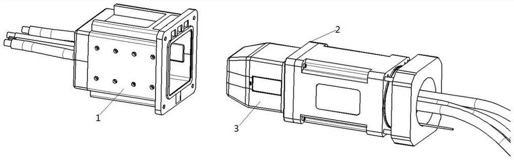
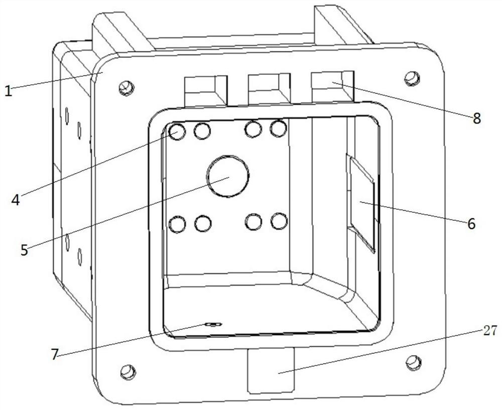
[0040] Such as figure 1 As shown, the present invention provides a DC charging connection device used in automatic charging, including a gun base conductive device and a gun tip conductive device, wherein, such as figure 2 As shown, the conductive device of the gun holder includes a gun holder housing 1 with an open end, an identification feature 8 is provided on the opening end surface of the gun holder housing 1, and a PE electrode mother part 5 is provided on the inner cavity wall of the gun holder housing 1 And the electrode protruding female part, preferably, the electrode protruding female part includes the signal electrode female part 4, the power electrode female part 6 and the CC1 electrode female part 7, wherein the PE electrode female part 5 and the signal electrode female part 4 are arranged on the gun seat In the same plane in th...


PUM


Abstract

The invention discloses a direct current charging connection device and method applied to automatic charging. The device comprises a gun seat shell with an opening at one end, wherein the opening end surface of the gun seat shell is provided with a recognition feature part and a visual mark, and the wall surface of an inner cavity of the gun seat shell is provided with a PE electrode female piece and an electrode projection female piece. The device also comprises a gun head and a gun tail, wherein the outer surface of the gun head is provided with a PE electrode male piece and an electrode projection male piece, the electrode projection male piece can stretch out of the outer surface of the gun head or retract into an inner cavity of the gun head, the other end of the gun tail is connected with a visual positioning device and a laser radar, and the laser radar and the visual positioning device are both used for locking the coordinate pose of a gun seat conductive device; and in the charging state, the gun head is inserted into the inner cavity of the gun seat shell, the electrode projection male piece on the gun head is connected to the electrode projection female piece of the gun seat shell in a pressed mode, and the PE electrode male piece is connected to the PE electrode female piece in a pressed mode. Through double positioning of visual positioning and laser radar and crimping of the electrode male piece and the electrode female piece, the plugging error of the gun head and the gun seat is reduced.

Description

technical field [0001] The invention belongs to the field of automatic charging, in particular to a direct current charging connection device and method applied in automatic charging. Background technique [0002] At present, there are two ways to realize automatic charging and conductive transmission. The first wireless charging adopts the DC wireless charging mode. The secondary side module needs to be installed on the new energy vehicle body, and the charging pile is connected to the primary side module. Get the cooperation of the car company. The second is to use a high-precision visual positioning charging robot with a national standard charging gun head to charge new energy vehicles. [0003] At present, the technical problems of automatic charging and conductive transmission of new energy vehicles generally have the following points: [0004] 1. To adopt the DC wireless charging mode, the primary side module needs to be installed on the ground, and the secondary sid...

Claims


Application Information

Patent Timeline
IPC IPC(8): H01R13/631H01R13/02B60L53/16
CPCB60L53/16H01R13/02H01R13/631Y02T10/70Y02T10/7072Y02T90/14
Inventor 战春程
Owner 西安蓝豆新能源科技有限公司
Why Eureka
Try Eureka