Side coupled cavity measuring device and side coupled cavity measuring method for coupled cavity acceleration structure

A side-coupled cavity and measurement device technology, applied in the field of side-coupled cavity measurement devices, can solve problems such as difficulty in obtaining accurate test results of the side-coupled cavity, and achieve the effect of accurate acquisition

Active Publication Date: 2021-05-07
CHINA INSTITUTE OF ATOMIC ENERGY
View PDF16 Cites 2 Cited by
  • Summary
  • Abstract
  • Description
  • Claims
  • Application Information

AI Technical Summary

Problems solved by technology

For the side coupled cavity in the coupled cavity acceleration structure, since the side coupled cavity and the accelerating cavity are not on the same axis, it is difficult to obtain accurate test results of the side coupled cavity by the piston probe method in the related art

Method used


Image

  • Side coupled cavity measuring device and side coupled cavity measuring method for coupled cavity acceleration structure
  • Side coupled cavity measuring device and side coupled cavity measuring method for coupled cavity acceleration structure
  • Side coupled cavity measuring device and side coupled cavity measuring method for coupled cavity acceleration structure

Examples


Embodiment Construction

[0031] In order to make the purpose, technical solution and advantages of the present invention clearer, the technical solution of the present invention will be clearly and completely described below in conjunction with the accompanying drawings of the embodiments of the present invention. Apparently, the described embodiment is one embodiment of the present invention, but not all of them. Based on the described embodiments of the present invention, all other embodiments obtained by persons of ordinary skill in the art without creative efforts shall fall within the protection scope of the present invention.

[0032] It should be noted that, unless otherwise defined, the technical terms or scientific terms used in the present application shall have the usual meanings understood by those skilled in the field of the present invention. If the descriptions such as "first" and "second" are involved in the whole text, the descriptions such as "first" and "second" are only used to dis...


PUM


Abstract

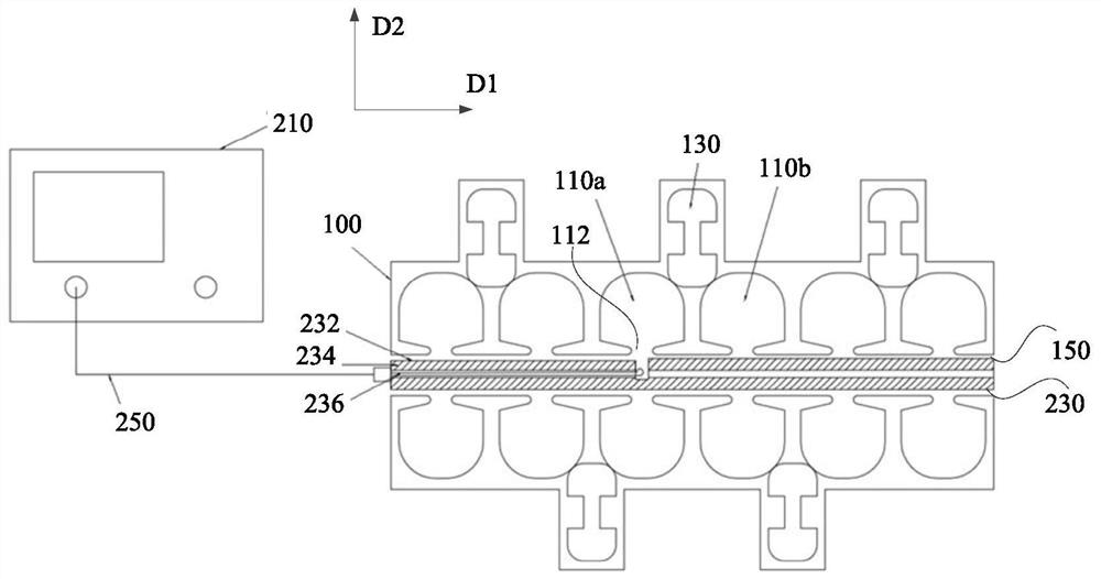
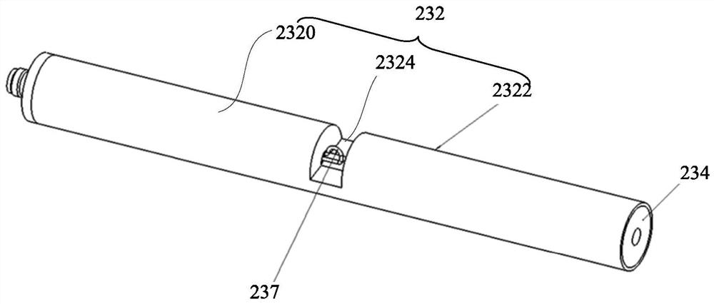
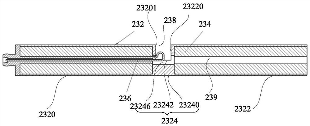
The invention discloses a side coupling cavity measuring device for a coupling cavity acceleration structure. The side coupling cavity measuring device comprises a network analyzer, a measuring part and a cable. The measuring part comprises a main body and a coaxial line; the main body is a copper pipe in which a groove is formed; a magnetic coupling ring is arranged at one end of the coaxial line; the coaxial line is located in the main body, and the magnetic coupling ring is located in the groove; the other end of the coaxial line is provided with a coaxial radio frequency connector; the coaxial radio frequency connector is connected with the network analyzer through the cable. According to the technical scheme, through the groove in the main body and the magnetic coupling ring located in the groove, complete short circuit of the acceleration cavities at the two sides of the side coupling cavity to be tested can be achieved, space can be reserved for microwave signal excitation and receiving devices, and therefore the test result of the edge coupling cavity can be accurately obtained.

Description

technical field [0001] The invention relates to the technical field of accelerators, in particular to a side-coupled cavity measurement device and a side-coupled cavity measurement method for a coupled-cavity acceleration structure. Background technique [0002] The coupled cavity accelerating structure is a proton linear accelerator, which is used to accelerate proton beams from tens of MeV to hundreds of MeV energies. A coupled-cavity accelerating structure generally includes multiple accelerating cavities, side-coupled cavities, bridge couplers and end-coupled cavities. In the coupled cavity accelerating structure, two adjacent accelerating cavities are connected through a side coupled cavity. In order to allow the microwave to enter each accelerating cavity through the transmission of the side coupling cavity and establish the designed accelerating electric field in each accelerating cavity, the parameters such as the cavity frequency of the accelerating cavity and the ...

Claims


Application Information

Patent Timeline
Patent Type & Authority Applications(China)
IPC IPC(8): G01R23/02
CPCG01R23/02
Inventor 杨誉杨京鹤
Owner CHINA INSTITUTE OF ATOMIC ENERGY
Why Eureka
Try Eureka