All-fiber current transformer and all-fiber current transformer unit

A current transformer, all-fiber technology, used in the measurement of current/voltage, voltage/current isolation, instruments, etc., can solve the problems of complex structure and low assembly efficiency of current transformers, so as to solve the problem of low assembly efficiency and improve installation. Efficiency, the effect of reducing installation steps

Pending Publication Date: 2021-05-07
HENAN PINGGAO ELECTRIC +2
View PDF10 Cites 0 Cited by
  • Summary
  • Abstract
  • Description
  • Claims
  • Application Information

AI Technical Summary

Problems solved by technology

[0004] The purpose of the present invention is to provide an all-fiber current transformer, which is used to solve the technical problem of low assembly efficiency caused by the current current transformer structure being relatively complex; All Fiber Optic Current Transformer Unit for Current Transformers

Method used


Image

  • All-fiber current transformer and all-fiber current transformer unit
  • All-fiber current transformer and all-fiber current transformer unit

Examples


specific Embodiment 1

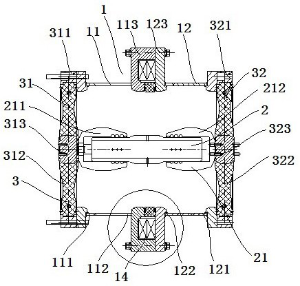
[0053] like figure 1 and figure 2 As shown, the all-fiber-optic current transformer unit includes an all-fiber-optic current transformer 1 , a central conductor 2 and an end insulator 3 .

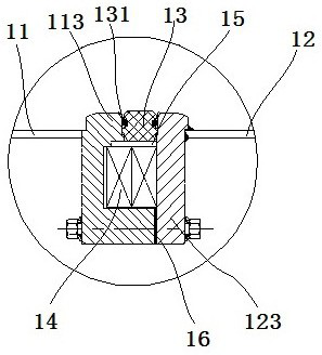
[0054] The all-fiber current transformer 1 includes a first cylinder 11 , a second cylinder 12 , an insulating ring 13 and a sensing ring 14 .

[0055] The first cylinder 11 has a first cylinder external end 111 and a first cylinder butt end 112, the second cylinder 12 has a second cylinder external end 121 and a second cylinder butt end 122, and the first cylinder external end 111 and the second barrel external end 121 are both connected to the external switchgear barrel, and the first barrel butt end 112 is detachably connected to the second barrel butt end 122 .

[0056] An annular block 113 is provided at the end of the first cylindrical body butt end 112, and an annular block 113 is provided with a groove opening toward the second cylindrical body butt end 122. The end of the second...

specific Embodiment 2

[0068] The only difference from the all-fiber-optic current transformer unit in Embodiment 1 above is that the cavity and the annular plate are fixedly connected by means of screw connection. In other embodiments, the metal ring and the external flange may also be connected by screws.

specific Embodiment 3

[0070] The only difference from the all-optical current transformer unit in the above-mentioned embodiment 1 is that the butt end of the first cylinder and the butt end of the second cylinder are both grooves, and the two grooves can be butted to form a sensor for the sensor ring to be placed in. Induction ring housing chamber. In other embodiments, the butt end of the first cylinder and the butt end of the second cylinder are in the shape of "L" and "7", and the abutment can form a sensing ring accommodating cavity for the sensing ring to be placed in.


PUM


Abstract

The invention relates to an all-fiber current transformer and an all-fiber current transformer unit. The all-fiber current transformer comprises a sensing ring, a first cylinder body, a second cylinder body and an insulating ring arranged between the first cylinder body and the second cylinder body, the insulating ring plays a certain role in supporting the fixed installation of the first cylinder body and the second cylinder body and also plays a role in electrical isolation, and the first cylinder body and the second cylinder body are prevented from forming a conductive loop. The interference of the induction current on the all-fiber current transformer is effectively avoided, and the precision of the all-fiber current transformer is improved. According to the all-fiber current transformer, the sensing ring containing cavity is defined after the first cylinder body and the second cylinder body are in butt joint, and the sensing ring is directly arranged in the sensing ring mounting cavity, so that the mounting steps are reduced, the structure of the all-fiber current transformer is simplified, and the technical problem that the assembling efficiency of an all-fiber current transformer unit is low due to the fact that an existing current transformer is complex in structure is solved.

Description

technical field [0001] The invention relates to an all-fiber current transformer and an all-fiber current transformer unit. Background technique [0002] Current transformers are used to measure the current in power systems. At present, electromagnetic current transformers are commonly used in GIS equipment. Electromagnetic current transformers are large in size and coil-wound current transformers are easily disturbed by external currents and have poor stability. . [0003] The Chinese patent with the authorized announcement number CN202583293U and the authorized announcement date of 2012.12.05 discloses a three-phase sub-box GIS all-optical current transformer, including a housing, a housing cover, an adapter housing, a shielding cylinder and an optical fiber transmission. Sensing ring, in which the transfer housing is fixed with the housing, and the optical fiber sensing ring is set in the housing. The all-fiber optic current transformer of this structure needs to assembl...

Claims


Application Information

Patent Timeline
Patent Type & Authority Applications(China)
IPC IPC(8): G01R19/00G01R15/24
CPCG01R19/00G01R15/24
Inventor 赵新科孟庆喜廉丽娟陈帅兵刘瑞瑞陈奕嘉岳光华李阳贺小维田超群王凯谢艳彬
Owner HENAN PINGGAO ELECTRIC
Why Eureka
Try Eureka