
Sealing machine for lubricating oil production

A technology of lubricating oil and sealing machine, applied in application, closure, household appliances, etc., can solve the problems of accelerated melting of aluminum foil, untimely heat dissipation, unfavorable sealing of aluminum foil, etc., to avoid high temperature heating, increase transmission speed, and improve sealing. the effect of

Inactive Publication Date: 2021-05-07
盐城市钊扬工业设计有限公司
View PDF0 Cites 1 Cited by
  • Summary
  • Abstract
  • Description
  • Claims
  • Application Information

AI Technical Summary

Problems solved by technology

[0003] The sealing box is the part used for heating, the installation position of the electromechanical inductance coil, because the inductance wire is wound in a ring to achieve heating, but because the sealing box is rectangular in process requirements, the lubricating oil bottle is transported through the conveyor belt The time is along a straight line, which will cause the heating at the gap between the coils and the sides of the bottle mouth to be inconsistent with the heating at the middle position, and as the bottle mouth increases and the number of coils increases. The heating effect of different parts is very different, so it is not conducive to the uniform and firm sealing of the aluminum foil. At the same time, when the temperature is high, due to the structure of the coil, the local aluminum foil will melt;
[0004] At the same time, during the heating process, due to the untimely heat dissipation or the failure of the heat dissipation device, the aluminum foil at the mouth of the lubricating oil bottle will melt faster due to continuous high temperature during heat sealing, and the consistency cannot be guaranteed. Therefore, it is necessary to carry out Control the heat of the bottle mouth when heated

Method used


Image

  • Sealing machine for lubricating oil production
  • Sealing machine for lubricating oil production
  • Sealing machine for lubricating oil production

Examples


Embodiment Construction

[0021] The following will clearly and completely describe the technical solutions in the embodiments of the present invention with reference to the accompanying drawings in the embodiments of the present invention. Obviously, the described embodiments are only some, not all, embodiments of the present invention. Based on the embodiments of the present invention, all other embodiments obtained by persons of ordinary skill in the art without making creative efforts belong to the protection scope of the present invention.

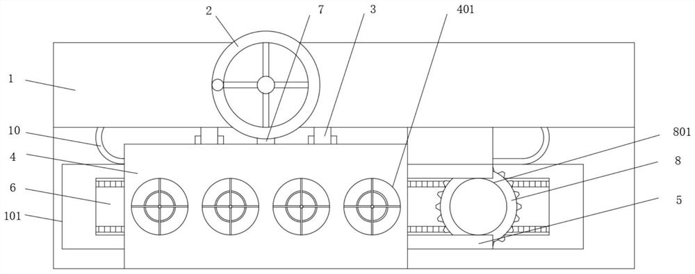
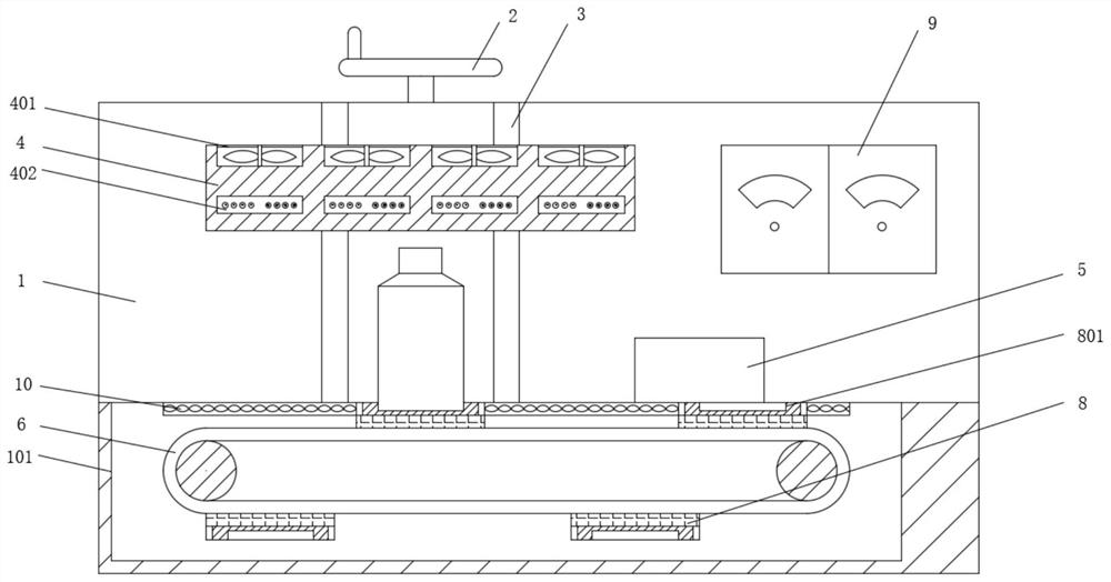
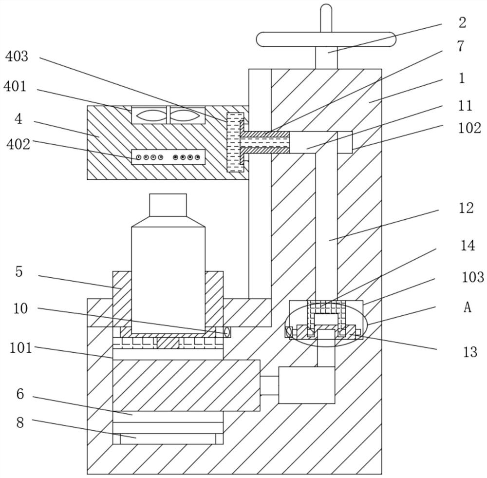
[0022] see Figure 1-6 , a sealing machine for lubricating oil production, comprising a body 1, an adjusting hand wheel 2 is movably installed on the top of the body 1, a lifting rod 3 is fixedly installed on one side of the front of the body 1, and a sealing box 4 is movably installed on the front of the lifting rod 3 The top of the sealing box 4 is provided with a heat dissipation port 401, the middle part of the sealing box 4 is fixedly installed with an in...


PUM


Abstract

The invention relates to the technical field of sealing equipment, and discloses a sealing machine for lubricating oil production. A working cavity is formed in the bottom of the front face of a machine body, a conveying belt is movably installed in the working cavity through a transmission mechanism, bearing gears are evenly installed on the outer side of the conveying belt at equal intervals, and a transmission chain is movably installed in a machine body. A liquid storage cavity is formed in the side, close to the back face, of the interior of a sealing box, a liquid guide pipe extending into the liquid storage cavity is fixedly installed at the position, between two lifting rods, of the front face of the machine body, and an L-shaped adjusting hole is formed in the position, located at the liquid guide pipe installation position, of the interior of the machine body. An adjusting cavity communicating with an adjusting hole is formed in the position, located at the bottom of the adjusting hole, in the machine body, an adjusting gear with one side engaged with the transmission chain is movably installed at the bottom of an inner cavity of the adjusting cavity, the top of the adjusting gear is movably sleeved with a pressing sleeve, and the sealing heating uniformity and the sealing quality are improved through a transmission structure and temperature adjustment.

Description

technical field [0001] The invention relates to the technical field of sealing equipment, in particular to a sealing machine for lubricating oil production. Background technique [0002] Lubricating oil is a kind of lubricating oil used in automobiles and mechanical equipment to reduce friction and protect it. Lubricating oil needs to be filled after production. In order to protect the lubricating oil, the lubricating oil after bottled For sealing, the commonly used sealing machine is an aluminum foil sealing machine. The current sealing machine has various structures but the principle is the same, that is, the aluminum foil at the bottle mouth is heated, melted and adhered to the bottle mouth by induction coil heating to achieve the sealing effect, but In practice, there are still some problems with such a structural design: [0003] The sealing box is the part used for heating, the installation position of the electromechanical inductance coil, because the inductance wire...

Claims


Application Information

Patent Timeline
IPC IPC(8): B67B6/00
CPCB67B6/00
Inventor 陈秀华
Owner 盐城市钊扬工业设计有限公司
Learn More