Water distribution device, fuel cell system and water distribution method of fuel cell system

A technology of fuel cell system and water separation device, which is applied in the direction of fuel cells, separation methods, chemical instruments and methods, etc., and can solve problems such as difficulty in fitting and adjustment, condensed liquid water entering the stack, and problems related to the overall performance of the stack

Pending Publication Date: 2021-05-07
BEIJING SINOHYTEC
View PDF2 Cites 2 Cited by
  • Summary
  • Abstract
  • Description
  • Claims
  • Application Information

AI Technical Summary

Problems solved by technology

[0007] However, in the prior art, installing a water separation structure in the stack (i.e. adding a bypass unit) will increase the length of the stack, affect the reliability of the internal seal of the stack, the distribution of contact pressure, and even affect the overall performance of the stack, and There are many variables affecting the implementation of this scheme, and it is difficult to adapt and adjust
[0008] Therefore, there is an urgent need to provide a water separation device, a fuel cell system and a water separation method thereof, so as to solve the above-mentioned problem that the condensed liquid water may enter the electric stack

Method used


Image

  • Water distribution device, fuel cell system and water distribution method of fuel cell system
  • Water distribution device, fuel cell system and water distribution method of fuel cell system
  • Water distribution device, fuel cell system and water distribution method of fuel cell system

Examples


Embodiment Construction

[0040] In order to make the technical problems solved by the present invention, the technical solutions adopted and the technical effects achieved clearer, the technical solutions of the embodiments of the present invention will be further described in detail below in conjunction with the accompanying drawings. Obviously, the described embodiments are only the technical solutions of the present invention. Some, but not all, embodiments. Based on the embodiments of the present invention, all other embodiments obtained by those skilled in the art without making creative efforts belong to the protection scope of the present invention.

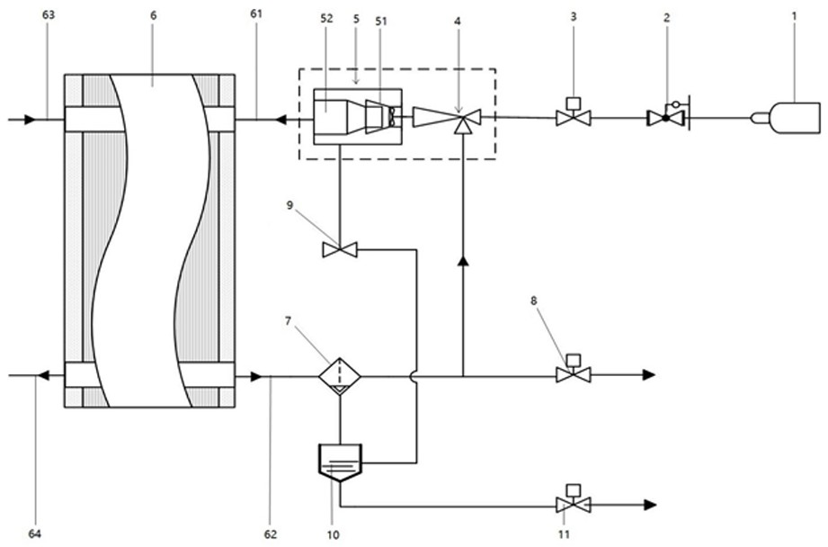
[0041] This embodiment provides a fuel cell system, such as figure 1 As shown, the fuel cell system includes an electric stack 6, a liquid separator, an ejector 4, a hydrogen storage device 1, and a water separation device 5. The electric stack 6 includes an anode inlet 61 and an anode outlet 62, and the anode inlet 61 and the water separation dev...


PUM


Abstract

The invention discloses a water distribution device, a fuel cell system and a water distribution method of the fuel cell system, belonging to the field of fuel cells. According to of the invention, an ejector of the fuel cell system and a gas inlet end of the water distribution device are integrally designed, the water distribution device comprises a tubular shell, a first water distribution piece and a second water distribution piece, gas is fed into a first end of the shell and discharged from a second end of the shell, the first water distribution piece is connected to the first end of the shell, gas enters an A end of the first water distribution piece and exits a B end of the first water distribution piece, the B end extends into the shell, rotational-flow blades are arranged in the A end, the second water distribution piece is connected to the second end of the shell, and the air inlet end of the second water distribution piece extends into an A-end port. When the rotational-flow blades rotate, the first water distribution piece forms a spiral airflow channel at the end A, liquid water drops are screwed out to the flow guide inner wall and flow towards the end B under blowing force, and a gaseous mixture obtained after water distribution enters a galvanic pile from the air outlet end of the second water distribution piece through the airflow channel. The water diversion device in an embodiment of the invention is good in water diversion effect and high in structural reliability.

Description

technical field [0001] The invention relates to the field of fuel cells, in particular to a water separation device, a fuel cell system and a water separation method thereof. Background technique [0002] In order to improve the performance of the fuel cell system, improve the utilization rate of hydrogen, and improve the water balance of the system, the anode recirculation system is adopted in the fuel cell system, that is, the anode hydrogen reaction gas of the fuel cell is excessively supplied to the stack, and the electrochemical reaction of the stack consumes part of the hydrogen, and the remaining hydrogen Together with the reaction product, it is mixed and discharged out of the stack, and the discharged mixture is driven back through the driving device (hydrogen circulation pump or ejector), mixed with the newly supplied hydrogen before the anode inlet of the stack, and re-enters the stack. The fuel cell stack is composed of hundreds of monolithic units. Each monolith...

Claims


Application Information

Patent Timeline
IPC IPC(8): B01D45/14H01M8/04119
CPCB01D45/14H01M8/04164Y02E60/50
Inventor 丁铁新闪念方川
Owner BEIJING SINOHYTEC
Why Eureka
Try Eureka