Office intelligent telephone system

A technology of smart phones and batteries, applied in the field of telephones, can solve the problems that conventional telephones cannot get rid of cables and cannot be moved.

Pending Publication Date: 2021-05-04
深圳市大而信科技有限公司
View PDF4 Cites 0 Cited by
  • Summary
  • Abstract
  • Description
  • Claims
  • Application Information

AI Technical Summary

Problems solved by technology

[0004] The purpose of the present invention is to provide an office smart phone system aimed at the technical defects of the prior art, so as to solve the technical problem that the conventional phone cannot get rid of the shackles of the cable and thus cannot be moved to different locations for use

Method used


Image

  • Office intelligent telephone system
  • Office intelligent telephone system
  • Office intelligent telephone system

Examples


Embodiment 1

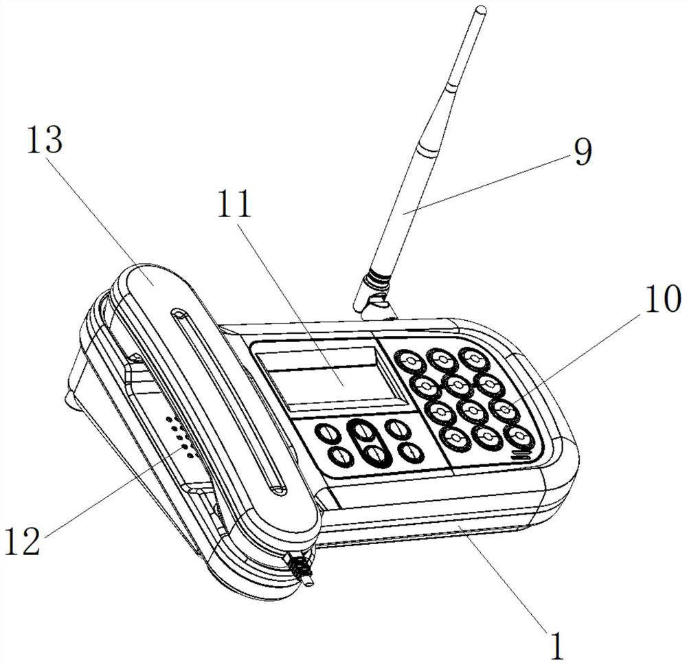
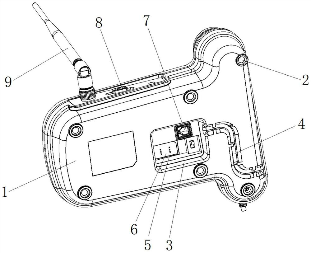
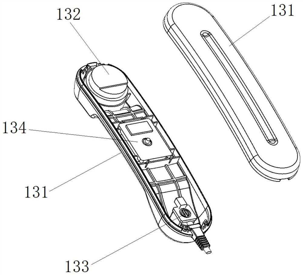
[0029] A smart phone system for office use, such as figure 1 , 2 , 4, and 5, including shell 1, rubber cap 2, groove 3, wire slot 4, SIM card slot 5, SIM card 6, cable slot 7, antenna 9, button assembly 10, display screen 11 , a through-hole array 12, an earpiece 13, a PCB board 14, a push button 15, a speaker 16, and a battery 17, wherein a plurality of rubber caps 2 are fixedly connected to the bottom end of the housing 1, and there are recesses at the bottom end of the housing 1 respectively. Groove 3 and wire groove 4, one end of wire groove 4 extends in the groove 3, and the other end of wire groove 4 extends to the edge of housing 1; On the top wall of groove 3, there is SIM card groove 5, SIM card A SIM card 6 is inserted into the groove 5, and a cable slot 7 is arranged on the top wall of the groove 3, and the connector of the telephone line is inserted into the cable slot 7, and at least a part of the telephone line is located in the line slot 4 There is an antenna ...

Embodiment 2

[0032] A smart phone system for office use, such as Figure 1-5As shown, it includes housing 1, rubber cap 2, groove 3, wire slot 4, SIM card slot 5, SIM card 6, cable slot 7, antenna 9, key assembly 10, display screen 11, through-hole array 12. Earpiece 13, PCB board 14, push button 15, loudspeaker 16, battery 17, wherein, a number of rubber caps 2 are fixedly connected to the bottom end of the shell 1, and grooves 3 and wires are respectively provided at the bottom end of the shell 1. Slot 4, one end of the wire slot 4 extends into the groove 3, and the other end of the wire slot 4 extends to the edge of the housing 1; there is a SIM card slot 5 on the top wall of the groove 3, and the SIM card slot 5 is inserted A SIM card 6 is connected, and a cable slot 7 is provided on the top wall of the groove 3, and the connector of the telephone line is inserted into the cable slot 7, and at least a part of the telephone line is located in the line slot 4; The side end of 1 has an a...


PUM


Abstract

The invention provides an office intelligent telephone system. According to the technical scheme, a groove is formed in the bottom end of the machine body, the SIM card is arranged in the groove, the SIM card is connected into a mobile communication network, signals are received and transmitted through the antenna, and therefore the wireless communication function is independently provided; meanwhile, a cable slot is arranged in the groove and is connected with a telephone line in an inserting manner, so a conventional curing communication function is independently provided. Based on the principle, wireless communication can be carried out under the condition that a telephone line is not plugged, so cable constraint is eliminated. Besides, a rubber cap is additionally arranged at the bottom end of the telephone body, and the telephone body can be fixed on a smooth desktop through a suction cup principle, so that the possibility of falling of the telephone due to accidental touch is reduced. Besides, the telephone line is locally accommodated by using the line slot, and the accommodating site is close to the cable slot, so that the position of the telephone line connector cannot be bent due to external force.

Description

technical field [0001] The invention relates to the technical field of telephones, in particular to an office smart phone system. Background technique [0002] A telephone is a device that communicates remotely by sending and receiving sound. The telephone set is set on the user side of the starting point and the end point of the telephone communication, and is the user terminal equipment of the telephone network. After continuous development, the current telephone set has been able to conveniently realize the call and call functions between end users. Although their styles vary widely, they generally have sound and electricity interchange, off-hook identification, sending signals, ringing, electrical connection, etc. Features. In addition to the above-mentioned basic functions, the design of the telephone should match the use environment and user characteristics. For example, underground telephones generally need to be equipped with emergency power and emergency alarm but...

Claims


Application Information

Patent Timeline
IPC IPC(8): H04M1/02H04M1/15
CPCH04M1/0297H04M1/15
Inventor 郭庆彬彭柏
Owner 深圳市大而信科技有限公司
Why Eureka
Try Eureka