
High-enthalpy high-heat-flow ground simulation test device and test method

A ground simulation, high heat flow technology, used in measurement devices, aerodynamic tests, and testing of machine/structural components, etc., can solve problems such as low effective power input efficiency, difficulty in simulating high enthalpy test capabilities at the same time, and lack of test capabilities.

Active Publication Date: 2021-05-04
CHINA ACAD OF AEROSPACE AERODYNAMICS
View PDF7 Cites 1 Cited by
  • Summary
  • Abstract
  • Description
  • Claims
  • Application Information

AI Technical Summary

Problems solved by technology

The simulation capability of existing arc wind tunnel equipment has its limitations: conventional tubular arc heaters can only simulate medium-low enthalpy, high-pressure aerodynamic thermal environments; segmented arc heaters can simulate medium-enthalpy, medium-high pressure aerodynamic thermal environments; Laminated arc heaters can generally only simulate aerodynamic thermal environments with high enthalpy, medium and low pressure (less than or equal to 1Mpa)
At present, high-power arc heaters capable of simulating high enthalpy, high pressure, and high heat flow in the world are represented by the 70MW H3 high-voltage laminated arc heater of AEDC in the United States. , High-pressure free jet end ablation test, currently lacks relevant test capabilities in China
At the same time, the existing aerothermal ground tests in arc wind tunnels generally adopt the test method of supersonic free jet flow. The power on the thermal material itself is less than 1MW, and most of the energy is dissipated. It is difficult to simultaneously simulate high enthalpy (≥10MJ / kg) and high heat flow (10MW / m2) Test capability of aerodynamic thermal environment

Method used


Image

  • High-enthalpy high-heat-flow ground simulation test device and test method

Examples


Embodiment Construction

[0027] The present invention will be described in further detail below in conjunction with the accompanying drawings and embodiments. It should be understood that the specific embodiments described here are only used to explain the present invention, but not to limit the present invention. In addition, it should be noted that, for the convenience of description, only some structures related to the present invention are shown in the drawings but not all structures.

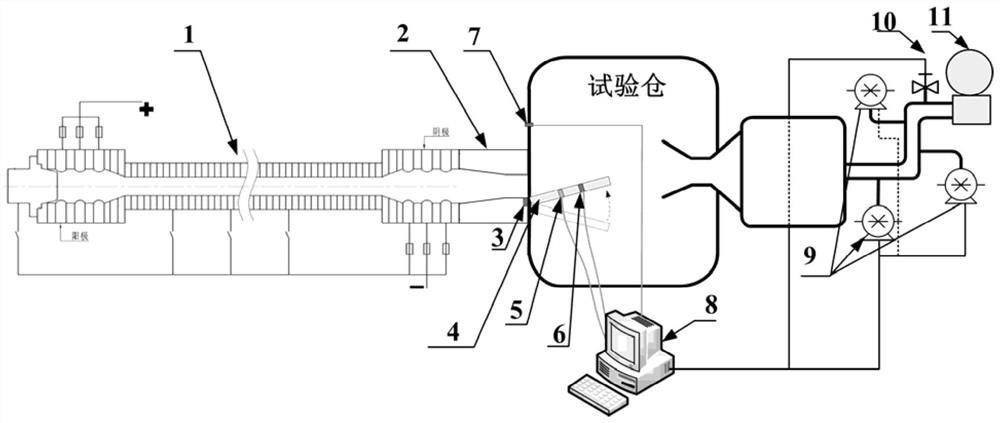
[0028] figure 1 It is a structural diagram of a high-enthalpy high-heat flow ground simulation test device in an embodiment of the present invention, including: an arc heater 1, a nozzle 2, a first pressure measurement device 3, a flat plate support 4, a heat flow measurement device 5, and a second pressure Measuring device 6 , third pressure measuring device 7 , data analysis terminal 8 , vacuum pump group 9 , vacuum valve 10 , spherical tank 11 .

[0029] The arc heater 1 heats the incoming test medium to form ...


PUM


Abstract

The invention relates to a high-enthalpy high-heat-flow ground simulation test device and test method. An arc heater heats an entering test medium to form high-temperature airflow, and the high-temperature airflow is expanded and accelerated by a spray pipe to generate a rectangular section subsonic airflow at an outlet of the spray pipe, a first pressure measuring device and a third pressure measuring device respectively measure the outlet pressure P1 of the spray pipe and the vacuum pressure P2 of a test chamber and feed back the pressure P1 and the pressure P2 to a data analysis terminal in real time, and the data analysis terminal gives an instruction according to P1 and P2 values and adjusts the operation parameters of a vacuum pump set and a vacuum valve until the vacuum pressure P2 of the test chamber is matched with the outlet pressure P1 of the spray pipe, a stable working state can be ensured for the subsonic airflow at the outlet of the spray pipe; the data analysis terminal sends an instruction to control a panel support to be adjusted from a negative attack angle to a positive attack angle, a heat flow measuring device and a second pressure measuring device arranged on a panel support measure the surface heat flow value q and the pressure P3 of the panel support in real time and feed back the values to the data analysis terminal, and the needed high heat flow ground simulation test environment is obtained.

Description

technical field [0001] The invention relates to a high-enthalpy and high-heat-flow ground simulation test device, which belongs to the research field of aircraft ground aerodynamic thermal tests. Background technique [0002] The reentry speed of a hypersonic vehicle reaches 7km / s-8km / s, and it faces an aerodynamic and thermal environment with high enthalpy and high heat flow of several 10MW / m2, which puts strict requirements on the simulation capabilities of ground test equipment. The simulation capability of existing arc wind tunnel equipment has its limitations: conventional tubular arc heaters can only simulate medium-low enthalpy, high-pressure aerodynamic thermal environments; segmented arc heaters can simulate medium-enthalpy, medium-high pressure aerodynamic thermal environments; Laminated arc heaters generally can only simulate aerodynamic thermal environments with high enthalpy, medium and low pressure (less than or equal to 1Mpa). At present, high-power arc heate...

Claims


Application Information

Patent Timeline
IPC IPC(8): G01M9/04
CPCG01M9/04Y02T90/00
Inventor 曾徽周凯闫宪翔杨国铭欧东斌
Owner CHINA ACAD OF AEROSPACE AERODYNAMICS
Learn More