Foaming device achieving porous air intake and exhaust and foaming method of foaming device

A foaming device, air intake and exhaust technology, applied in the foaming device and its foaming field, can solve the problems of less steam inlet and steam outlet, uneven heating of foam particles, uneven heating of raw materials, etc., so as to improve quality and energy utilization. High rate, uniform temperature effect

Inactive Publication Date: 2021-05-04
HANGZHOU FUYANG DONGSHAN PLASTIC MACHINERY
View PDF9 Cites 2 Cited by
  • Summary
  • Abstract
  • Description
  • Claims
  • Application Information

AI Technical Summary

Problems solved by technology

However, the existing foaming devices still have the problems of low foaming efficiency, uneven heating of raw materials and high energy consumption.
[0003] The Chinese patent with the publication number CN201042837 discloses an EPS foaming machine, which includes a feeding mechanism, a foaming tank, a drying bed, connecting pipelines between various components and a control system, and the steam on the foaming tank There are few inlets and steam outlets, low foaming efficiency, and uneven heating of foam particles; the Chinese patent with the publication number CN207140200U discloses a high-efficiency steam pre-foaming machine, which is set by a spiral stirring belt and a mixing barrel, When the device is pre-foaming the material, the material in the mixing tank can be heated evenly, so as to ensure the foaming quality of the material. The steam inlet and steam outlet on the mixing tank of the invention are less, and the foaming efficiency is low.

Method used


Image

  • Foaming device achieving porous air intake and exhaust and foaming method of foaming device
  • Foaming device achieving porous air intake and exhaust and foaming method of foaming device
  • Foaming device achieving porous air intake and exhaust and foaming method of foaming device

Examples


Embodiment Construction

[0029] The present invention will be further described in detail below in conjunction with the accompanying drawings and examples. The following examples are explanations of the present invention and the present invention is not limited to the following examples.

[0030] Example.

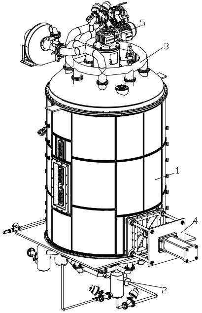
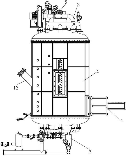
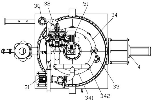
[0031] see Figure 1 to Figure 6 , the foaming device of porous intake and exhaust in the present embodiment comprises foam barrel 1, air intake mechanism 2, exhaust mechanism 3, material door cylinder 4 and stirring mechanism 5; Foam barrel 1 is provided with feed port 12 The intake mechanism 2 is installed at the bottom of the foaming barrel 1; the exhaust mechanism 3 is installed at the top of the foaming barrel 1;

[0032] The intake mechanism 2 in the present embodiment comprises a total intake pipe 20, No. 1 filter 21, No. 2 filter 22, No. 1 steam bag 23, No. 2 steam bag 24, No. 3 steam bag 25, pressure reducing valve 26, Steam proportional valve 27, air proportional valve 28 and porous air...


PUM


Abstract

The invention relates to a foaming device achieving porous air intake and exhaust and a foaming method of the foaming device. In order to solve the problems that in the prior art, a foaming device is low in foaming efficiency and high in energy consumption, according to the technical scheme, the foaming device achieving porous air intake and exhaust comprises a foaming barrel, an air intake mechanism, an exhaust mechanism, a material door cylinder and a stirring mechanism; a feeding opening is formed in the foaming barrel; the air intake mechanism is mounted at the bottom of the foaming barrel; the exhaust mechanism is mounted at the top of the foaming barrel; the material door cylinder is mounted at a material door of the foaming barrel; the air intake mechanism comprises a main air intake pipe, a first filter, a second filter, a first steam pocket, a second steam pocket, a third steam pocket, a pressure reducing valve, a steam proportional valve, an air proportional valve and a porous air intake pipeline; the main air intake pipe is connected with the first filter; the first filter is connected with the first steam pocket and the second steam pocket; the first steam pocket and the second steam pocket are connected in parallel; and the second filter is connected with the first steam pocket and the second steam pocket. The foaming device is high in foaming efficiency and achieves energy saving and environment protection.

Description

technical field [0001] The invention relates to a foaming device and a foaming method thereof, in particular to a foaming device for porous air intake and exhaust and a foaming method thereof. Background technique [0002] At present, when the foaming device on the market is working, steam with a certain temperature is generally introduced into the foaming tank. After a certain period of time, the EPS hard particles will expand into light foam particles; when the foam particles reach the specified After the density is reached, open the discharge port of the foaming tank to discharge the material. However, the existing foaming device still has the problems of low foaming efficiency, uneven heating of raw materials and high energy consumption. [0003] The Chinese patent with the publication number CN201042837 discloses an EPS foaming machine, which includes a feeding mechanism, a foaming tank, a drying bed, connecting pipelines between various components and a control system...

Claims


Application Information

Patent Timeline
Patent Type & Authority Applications(China)
IPC IPC(8): B29C44/34
CPCB29C44/34
Inventor 徐元朝
Owner HANGZHOU FUYANG DONGSHAN PLASTIC MACHINERY
Why Eureka
Try Eureka