Metal paint production equipment

A technology for production equipment and metal coatings, applied in the direction of mixers, dissolution, chemical instruments and methods, etc., can solve the problems of limited grinding range of grinding balls, poor grinding effect, inability to touch and grind metal coatings, etc.

Pending Publication Date: 2021-05-04
吴小娅
View PDF10 Cites 0 Cited by
  • Summary
  • Abstract
  • Description
  • Claims
  • Application Information

AI Technical Summary

Problems solved by technology

[0003] The existing patent No. CN108855455B proposes a water-based paint grinding device, which realizes the grinding and mixing of metal paint through the setting of multiple mechanisms, but when it uses the reciprocating production process of stirring and grinding, it needs to operate equipment or transport metal paint , to realize the reciprocating processing of metallic paint in the stirring mechanism and the grinding mechanism, the operation efficiency is low
[0004] The existing patent No. CN105597883B proposes a paint stirring and grinding mechanism, which has the advantages of uniform stirring, etc., but it only uses the grinding balls arranged at the bottom to realize the grinding function. The grinding range of the grinding balls is limited, and the contact amount with the metal paint is actually very small. Less, unable to touch and grind most metal coatings, resulting in poor grinding effect

Method used


Image

  • Metal paint production equipment
  • Metal paint production equipment
  • Metal paint production equipment

Examples


Embodiment Construction

[0037] The following will clearly and completely describe the technical solutions in the embodiments of the present invention with reference to the accompanying drawings in the embodiments of the present invention. Obviously, the described embodiments are only some, not all, embodiments of the present invention. Based on the embodiments of the present invention, all other embodiments obtained by persons of ordinary skill in the art without making creative efforts belong to the protection scope of the present invention.

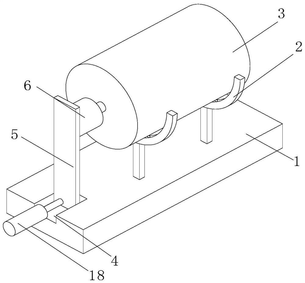
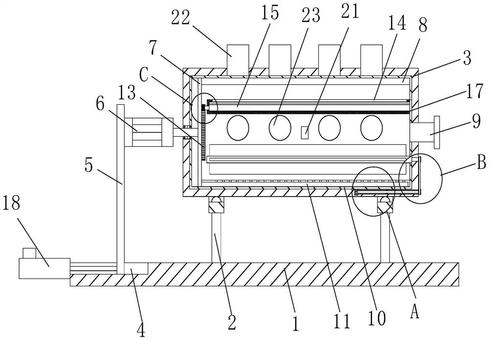
[0038] see Figure 1-10 , the present invention proposes a metal paint production equipment, comprising a bottom plate 1, the top surface of the bottom plate 1 is fixedly connected with a support frame 2, the top of the support frame 2 is in the form of a semi-circular ring, and the inner wall of the top surface of the support frame 2 is sleeved with a barrel 3. The barrel 3 is a hollow cylinder, and the left top surface of the bottom plate 1 is provided with ...


PUM


Abstract

The invention relates to the technical field of metal paint, and discloses metal paint production equipment which comprises a bottom plate, the top surface of the bottom plate is fixedly connected with a supporting frame, the top end of the supporting frame is a semicircular ring body, the inner wall of the top surface of the supporting frame is sleeved with a material barrel, a sliding groove is formed in the top surface of the left side of the bottom plate, a sliding plate is sleeved in the sliding groove, the face, opposite to the material barrel, of the sliding plate is fixedly connected with a rotating motor, a hole is formed in the center of the left side of the material barrel, a rotating bearing is fixedly installed in the hole, the rotating bearing is fixedly connected with a transmission shaft of the rotating motor, a stirring disc is fixedly connected to the end, located in the material barrel, of the transmission shaft of the rotating motor, and two stirring rods are fixedly connected to the right side face of the stirring disc; and the right side face of the material barrel is fixedly connected and communicated with a feeding barrel A. Through the arrangement of a stirring rod, raw materials are scraped into a grinding barrel from the bottom in a layered mode, the ground raw materials are then spread on the upper layer to be prevented from being mixed with unground raw materials, and therefore, the grinding range and the overall grinding effect of the raw materials are guaranteed.

Description

technical field [0001] The invention relates to the technical field of metal paint, in particular to a metal paint production equipment. Background technique [0002] Metallic paint is a paint with a metallic texture. The production process of metallic paint can be divided into stirring and grinding. [0003] The existing patent No. CN108855455B proposes a water-based paint grinding device, which realizes the grinding and mixing of metal paint through the setting of multiple mechanisms, but when it uses the reciprocating production process of stirring and grinding, it needs to operate equipment or transport metal paint , to realize the reciprocating processing of the metal paint in the stirring mechanism and the grinding mechanism, and the operation efficiency is low. [0004] The existing patent No. CN105597883B proposes a paint stirring and grinding mechanism, which has the advantages of uniform stirring, etc., but it only uses the grinding balls arranged at the bottom to...

Claims


Application Information

Patent Timeline
IPC IPC(8): B01F13/10B01F11/00
CPCB01F31/00B01F33/83B01F2101/30Y02P70/10
Inventor 不公告发明人
Owner 吴小娅
Why Eureka
Try Eureka