
Denitration reactor hoisted by magnetic force

A technology of denitration reactor and reactor shell is applied in the field of denitration reactor, which can solve the problems of inconvenient installation of catalyst modules, limitation of reactor size, and inapplicability of denitration reactors, etc.

Active Publication Date: 2021-05-04
CHINA PETROLEUM & CHEM CORP +1
View PDF12 Cites 0 Cited by
  • Summary
  • Abstract
  • Description
  • Claims
  • Application Information

AI Technical Summary

Problems solved by technology

However, this method has the following problems: (1) There are still a series of disadvantages caused by the use of steam soot blowing; (2) There are restrictions on the size of the reactor, which is not suitable for denitrification reactors with large flue gas volumes; (3) The supporting structure needs to occupy a large space, which is not applicable to the limited installation space
However, this method has problems such as inconvenient installation of the catalyst module, and dead areas on the catalyst tray.

Method used


Image

  • Denitration reactor hoisted by magnetic force
  • Denitration reactor hoisted by magnetic force
  • Denitration reactor hoisted by magnetic force

Examples


Embodiment 1

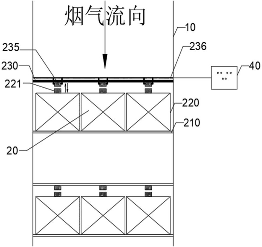
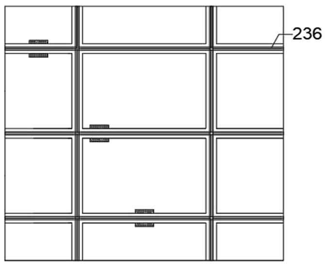
[0035] Such as Figure 1-6 As shown, a denitrification reactor using magnetic hoisting. In this embodiment, the SCR reactor is arranged vertically. The denitration reactor includes a vertically arranged cube-shaped reactor shell 10 and several catalyst beds 20 . The reactor shell can also be a polygonal or circular shell. Each catalyst bed layer includes a supporting beam 210 , a denitration catalyst module 220 and a catalyst lifting beam 230 . The projected center line of the catalyst hoisting beam 230 in the vertical direction passes through the center point of each catalyst module 220 , and the hoisting beam 230 communicates with the corresponding catalyst installation door 110 on the reactor shell of this layer.

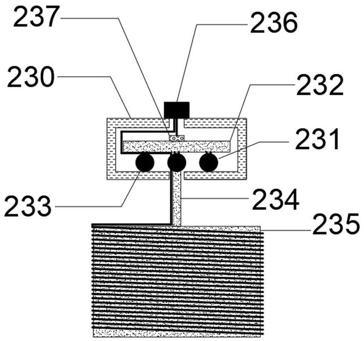
[0036] Several hoisting trolleys 231 are arranged below (parts) of the hoisting beam. The hoisting trolley includes a car body 232 and a universal wheel set 233, a boom 234 is set at the center of the bottom of the car body, and the car body is connected to t...


PUM


Abstract

The invention discloses a denitration reactor. The reactor comprises a reactor shell and a plurality of catalyst bed layers, each catalyst bed layer comprises a supporting beam, a catalyst module and a magnetic hoisting beam; more than one catalyst mounting door is arranged at the position, corresponding to each catalyst bed layer, of the reactor shell; the projection center line of the catalyst hoisting beam in the vertical direction penetrates through the center point of each catalyst module, and the hoisting beam is communicated with the catalyst mounting door of the layer; and the plurality of hoisting trolleys are arranged below the hoisting beam, electromagnetic modules are arranged at the lower parts of the hoisting trolleys, a magnet is arranged at the center above each catalyst module, and the electromagnetic modules are in one-to-one correspondence with the magnets on the catalyst modules below the electromagnetic modules. According to the denitration reactor, automatic installation of the catalyst module can be achieved, and meanwhile automatic ash removal operation of the denitration module can be achieved. The denitration reactor provided by the invention can reduce the height of the reactor or increase the filling amount of the catalyst.

Description

technical field [0001] The invention belongs to the technical field of waste gas denitrification, and in particular relates to a denitrification reactor hoisted by magnetic force. Background technique [0002] Many industrial flue gases contain a large amount of nitrogen oxides. Nitrogen oxides are easily discharged into the atmosphere to form acid rain and photochemical smog, which brings harm to the ecological environment and human health. Domestic control of NOx emissions is becoming increasingly stringent. [0003] Selective catalytic reduction (SCR) method is currently the most important dry flue gas denitrification technology in industrial applications. SCR denitrification technology is a process in which reducing gas NH3 reacts with NOx in flue gas to generate nitrogen and water under the action of a solid catalyst within a suitable temperature range. SCR denitrification technology is widely used because of its advantages of convenient operation, simple implementati...

Claims


Application Information

Patent Timeline
Patent Type & Authority Applications(China)
IPC IPC(8): B01D53/86B01D53/88B01D53/56
CPCB01D53/8631B01D53/885B01D2258/0283
Inventor 高峰贠莹李欣
Owner CHINA PETROLEUM & CHEM CORP
Learn More