
Swing mechanism capable of dividing silicon wafers into columns

A swing mechanism and silicon wafer technology, which is applied in the manufacture of conveyor objects, electrical components, semiconductor/solid-state devices, etc., can solve the problems affecting the loading efficiency and the limited number of wafer baskets, so as to reduce the probability of silicon wafer fragments and ensure continuous The effect of uploading film and increasing storage capacity

Pending Publication Date: 2021-04-30
TIANJIN HUANBO SCI & TECH CO LTD
View PDF0 Cites 0 Cited by
  • Summary
  • Abstract
  • Description
  • Claims
  • Application Information

AI Technical Summary

Problems solved by technology

[0002] In the existing technology, it is necessary to replace a new basket to continue loading after the basket is filled with film. The empty baskets are arranged in sequence. Due to the limited position of the basket lifting mechanism, the number of baskets that can be accommodated is limited. , it is necessary to replace the film basket frequently, which will easily affect the film loading efficiency

Method used


Image

  • Swing mechanism capable of dividing silicon wafers into columns
  • Swing mechanism capable of dividing silicon wafers into columns
  • Swing mechanism capable of dividing silicon wafers into columns

Examples


Embodiment

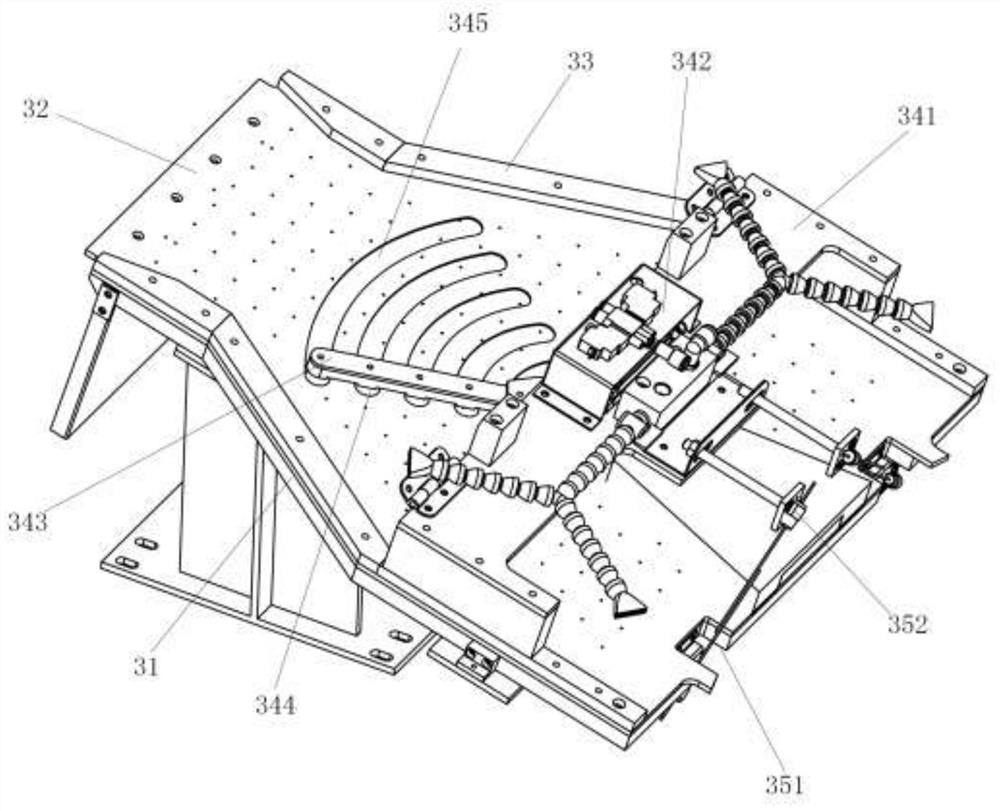
[0027] Embodiment: A swing mechanism for separating silicon wafers, which is arranged upstream of the wafer basket, includes a water injection base 31, a water spray cover 32 and a swing device, the water injection base 31 is arranged obliquely, the water injection base 31 and the water spray cover 32 have the same shape, and both sides are tightly fixed by pressing blocks 33. The pressing blocks 33 on both sides of the front end of the water spray cover 32 form the inlet of the silicon wafer, and the pressing blocks 33 on both sides of the rear end of the water spraying cover 32 form the outlet of the silicon wafer. The water injection substrate 31 A water tank is provided on the water injection base plate 31. A penetrating water injection pipe is provided on the water injection base plate 31. The water injection pipe communicates with the water tank. The water spray cover plate 32 is covered and arranged on the water injection base plate 31. The position of the water outlet p...


PUM


Abstract

The invention relates to a swing mechanism capable of dividing silicon wafers into columns. The swing mechanism is arranged on the upstream of a silicon wafer basket and comprises a water injection base plate, a water spraying cover plate and a swing device, the water injection base plate is obliquely arranged, a water tank is arranged on the water injection base plate, a through water injection pipe is arranged on the water injection base plate, the water injection pipe is communicated with the water tank, and the water spraying cover plate covers the water injection base plate. Through water outlet pipes are arranged on the water spraying cover plate, and the multiple water outlet pipes are matched with the water tank in position; and the swing device is arranged on the outer side of the water spraying cover plate and comprises a beam, a swing air cylinder and a swing rod, the swing rod is arranged on the lower side of the beam, and the swing air cylinder is arranged on the upper surface of the beam and connected with the swing rod which is tightly attached to the water spraying cover plate. The swing mechanism has the beneficial effects that turning two-side wafer loading is achieved through swinging of the swing rod, continuous wafer loading can be achieved, and the time for waiting for an empty wafer basket to be in place when the wafer basket full of silicon wafers is taken away is shortened; and the wafer basket storage amount of the equipment is increased, and the manual frequent basket taking and basket loading operation time is shortened.

Description

technical field [0001] The invention belongs to the field of silicon wafer manufacturing equipment, in particular to a swing mechanism capable of separating silicon wafers. Background technique [0002] In the existing technology, it is necessary to replace a new basket to continue loading after a basket is filled during loading. The empty baskets are arranged in sequence. Due to the limited position of the basket lifting mechanism, the number of baskets that can be accommodated is limited. , it is necessary to replace the film basket frequently, which will easily affect the film loading efficiency. Contents of the invention [0003] The problem to be solved by the present invention is to provide a swing mechanism capable of separating silicon wafers. [0004] In order to solve the above-mentioned technical problems, the technical solution adopted by the present invention is: a swing mechanism for separating silicon wafers, which is arranged upstream of the wafer basket, ...

Claims


Application Information

Patent Timeline
IPC IPC(8): H01L21/67H01L21/677
CPCH01L21/67271H01L21/67781
Inventor 靳立辉尹擎任志高王国瑞杨骅王思雨姚长娟李博樊赛
Owner TIANJIN HUANBO SCI & TECH CO LTD
Learn More