Large-span bridge nonlinear swing analysis equipment based on cloud computing

An analytical equipment and large-span technology, applied in the direction of measuring inclination, measuring devices, instruments, etc., can solve the problems of difficult to install bridges in various areas and large volumes

Pending Publication Date: 2021-04-30
王光柱
View PDF0 Cites 0 Cited by
  • Summary
  • Abstract
  • Description
  • Claims
  • Application Information

AI Technical Summary

Problems solved by technology

[0004] The purpose of the present invention is to solve the shortcomings of the equipment used to detect and analyze the swing amplitude of bridges in the prior art, which are relatively large and difficult to be flexibly installed in various areas of the bridge, and propose a non-linear long-span bridge based on cloud computing Swing Analysis Equipment

Method used


Image

  • Large-span bridge nonlinear swing analysis equipment based on cloud computing
  • Large-span bridge nonlinear swing analysis equipment based on cloud computing
  • Large-span bridge nonlinear swing analysis equipment based on cloud computing

Examples


Embodiment 1

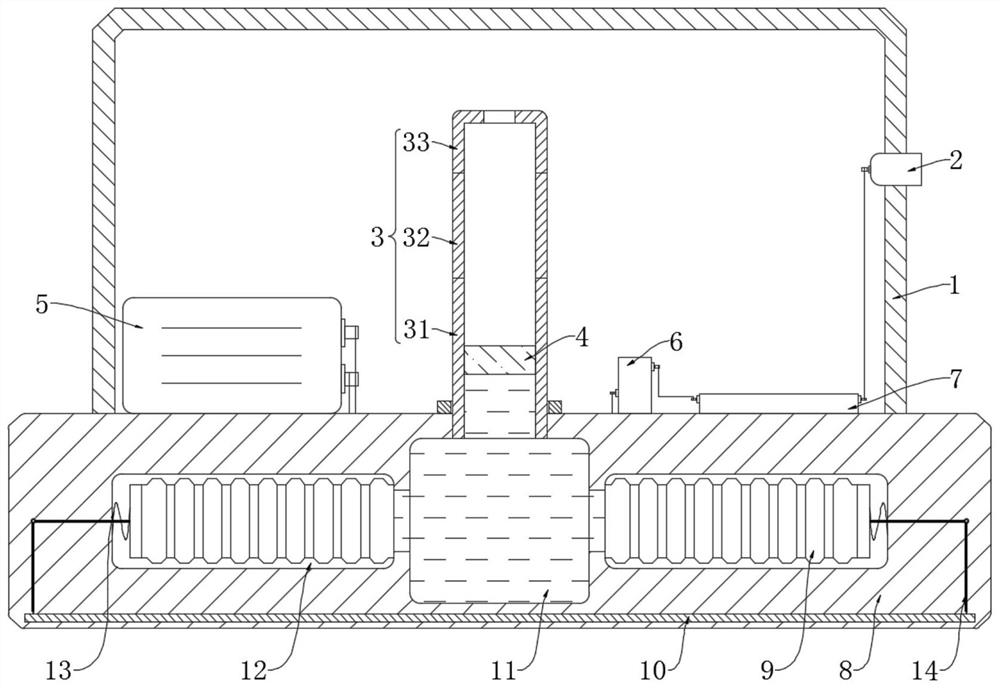
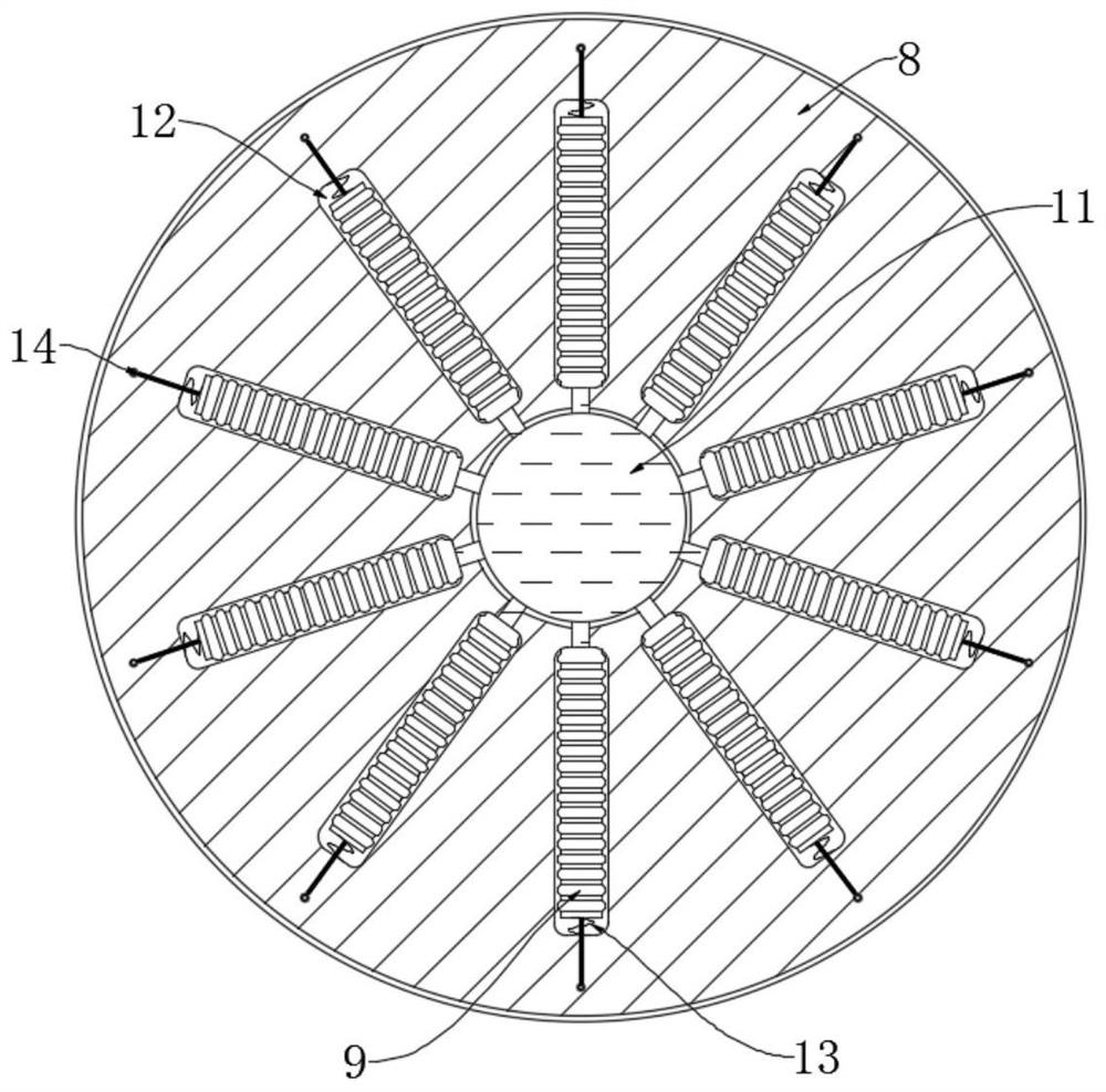
[0025] refer to Figure 1-2 , a non-linear swing analysis device for long-span bridges based on cloud computing, including a protective housing 1 and a base 8, the protective housing 1 is sealed and installed above the base 8, and the base 8 is provided with a diversion chamber 11 and a plurality of shunts chamber 12, and a plurality of shunt chambers 12 are circumferentially distributed with respect to the shunt chamber 11, and each shunt chamber 12 is equipped with a telescopic tube 9 communicating with the shunt chamber 11, and each telescopic pipe 9 is far away from the side of the shunt chamber 11. A spring 13 is fixedly connected between one end and the inner wall of the corresponding distributing chamber 12 , and the spring 13 is in a compressed state when the base 8 is horizontal.

[0026] In this embodiment, the end of each telescopic tube 9 connected to the corresponding spring 13 is embedded with a metal circular plate to prevent deformation of the end connected to ...

Embodiment 2

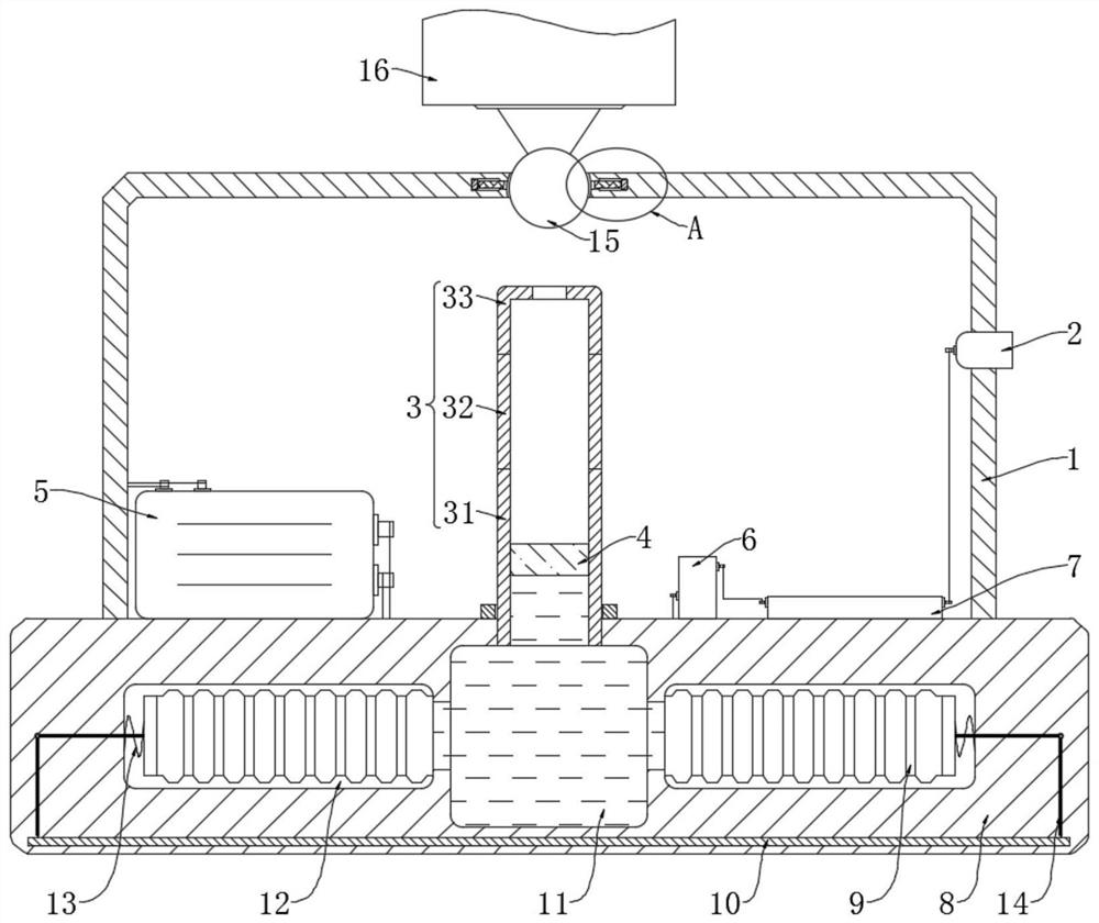
[0035] refer to Figure 3-4 The difference between this embodiment and Embodiment 1 is that: a mounting seat 16 is provided above the protective housing 1, and the lower surface of the mounting seat 16 is fixedly connected with a rotating bead 15, and the rotating bead 15 is connected to the top wall of the protective housing 1. Rotationally connected, the top wall of the protective shell 1 is symmetrically provided with a plurality of chute 17, and the plurality of chute 17 is symmetrically distributed around the rotating bead 15, and each chute 17 is equipped with an electromagnet 18 and a fixed column 19. The fixed column 19 is made of a bar magnet, and a non-slip rubber sleeve is glued on the outside.

[0036] This embodiment can illustrate its functional principle through the following operation mode: when the equipment is installed on an arched bridge, first fix the mounting base 16 somewhere on the bridge, so that the protective shell 1 and the base 8 are in a suspended...


PUM


Abstract

The invention discloses a large-span bridge nonlinear swing analysis device based on cloud computing. The device comprises a protective shell and a base, wherein the protective shell is hermetically mounted above the base, a diversion cavity and a plurality of shunt cavities are formed in the base, and the plurality of shunt cavities are distributed in the circumferential direction of the diversion cavity; and a telescopic pipe communicating with the flow turning cavity is installed in each flow dividing cavity, and a spring is fixedly connected between the end, away from the flow turning cavity, of each telescopic pipe and the inner wall of the corresponding flow dividing cavity. The device is small in size, can be flexibly applied to all positions of a bridge, can automatically detect and analyze the swing amplitude of the bridge, intelligently judges whether a prompt or alarm signal needs to be sent out or not, enables driving to be safer, does not need complex leveling work even if the device is installed on the arched bridge, and is high in practicability. Only the protective shell and the base need to be in a suspended state, and time and labor can be effectively saved.

Description

technical field [0001] The invention relates to the technical field of cloud computing equipment, in particular to a cloud computing-based nonlinear swing analysis equipment for long-span bridges. Background technique [0002] With the rapid development of technologies such as mountain-building and bridge-building, the length of bridges has been continuously broken, and some bridges have even crossed rivers or seas. When the wind blows over the bridge, the wind on both sides of the bridge is likely to cause " Karman vortex street phenomenon, which causes the nonlinear swing of the bridge. [0003] Although nonlinear swing of long-span bridges is a relatively common phenomenon, when the swing amplitude exceeds the threshold, the bridge structure may be damaged, and it is very unsafe for vehicles to drive on the bridge. Therefore, timely detection of bridge swing The amplitude is very necessary. The existing detection and analysis equipment is large in size, difficult to fix,...

Claims


Application Information

Patent Timeline
IPC IPC(8): G01C9/18G01C9/06
CPCG01C9/06G01C9/18G01C2009/182
Inventor 王光柱
Owner 王光柱
Why Eureka
Try Eureka