Device for applying lubricating grease to inner wall of pipeline

An oiling device and grease technology, which is applied in lubricating parts, engine lubrication, delivery pipes/joints, etc., can solve problems such as high viscosity of grease, heavy oiling labor, secondary pollution of products, etc., to ensure smearing Area, high oiling efficiency, effect of improving smearing effect

Active Publication Date: 2021-04-30
CHANGZHOU KAIDI ELECTRICAL INC
View PDF7 Cites 1 Cited by
  • Summary
  • Abstract
  • Description
  • Claims
  • Application Information

AI Technical Summary

Problems solved by technology

[0002] The commonly used methods of oiling the grease on the inner wall of the steel pipe are spray or smear. The spray type needs to be in a closed space. The mist grease generated by the spray type is easy to pollute the surface of other products in the air. The grease has a high viscosity and is not easy to Cleaning will cause secondary pollution of the product. However, the existing smear-type oiling is prone to problems such as grease accumulation, uneven grease, labor-intensive oiling, low efficiency, and waste of grease.

Method used


Image

  • Device for applying lubricating grease to inner wall of pipeline
  • Device for applying lubricating grease to inner wall of pipeline
  • Device for applying lubricating grease to inner wall of pipeline

Examples


Embodiment 1)

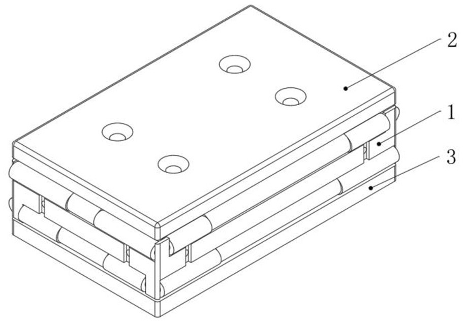
[0037] See Figure 1 to Figure 5 , The present invention has a main oil plate 1, a first cover plate 2, a second cover plate 3, and an elastic oiling mechanism 4. The main oil plate 1, the first cover plate 2 and the second cover plate 3 have a rectangular cross-sectional shape along the inside of the oiling pipe, and are suitable for painting the inner wall of the rectangular pipe.

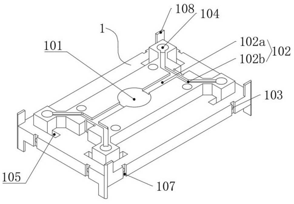
[0038] The main oil plate 1 includes an oil inlet hole 101, a main oil plate flow channel 102, and an oil outlet hole 103. The oil inlet hole 101 is arranged on the main oil plate 1, and the main oil plate flow channel 102 is arranged on the main oil plate 1. There are 8 oil holes 101 and oil outlet holes 103, all of which are distributed on the main oil plate 1 side. The size of the main oil plate 1 is 2mm smaller than the inner wall size of the pipeline to be oiled.

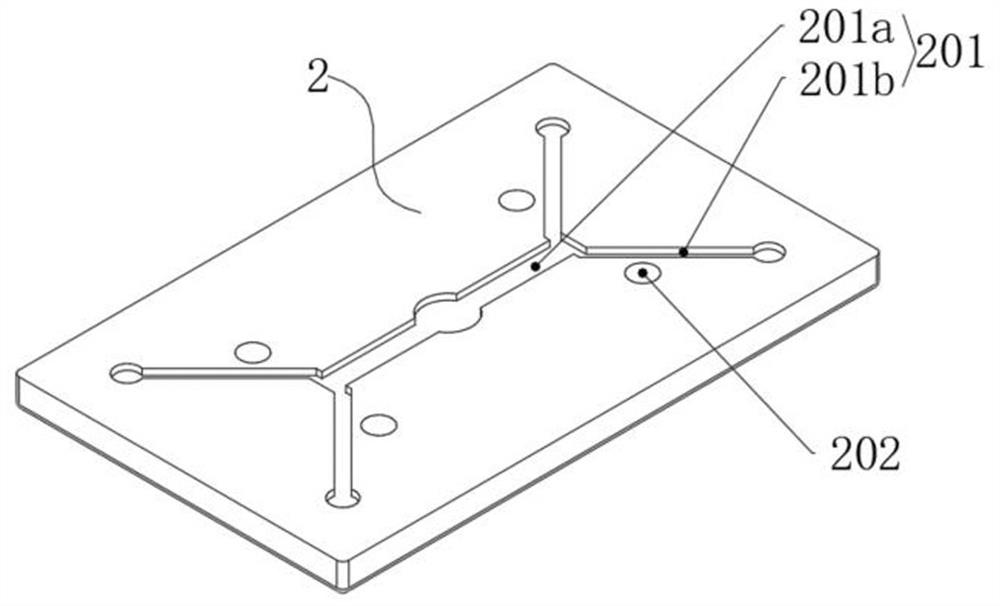
[0039] The first cover plate 2 is fixed above the main oil plate 1 .

[0040] The second cover plate 3 is fixed below the mai...

Embodiment 2)

[0051] See Figure 9 and Figure 10 , This embodiment is basically the same as Embodiment 1, and its distinguishing feature is that the cross-sectional shape of the main oil plate 1, the first cover plate 2 and the second cover plate 3 along the inside of the oiling pipe is a square, which is suitable for painting the inner wall of a square pipe.

Embodiment 3)

[0053] See Figure 11 and Figure 12 , this embodiment is basically the same as Embodiment 1, and its distinguishing features are: the cross-sectional shape of the main oil plate 1, the first cover plate 2 and the second cover plate 3 along the inside of the oiling pipe is an oblong hole shape, and the roller 403 at the arc-shaped end It is drum-shaped. Suitable for coating the inner wall of oblong hole tubes.


PUM


Abstract

The invention relates to the technical field of grease applying of the inner wall of a pipeline, in particular to a device for applying lubricating grease to the inner wall of the pipeline. The device comprises a main oil plate, a first cover plate, a second cover plate and elastic grease applying mechanisms, wherein the main oil plate comprises an oil inlet hole, a main oil plate flow channel and oil outlet holes, wherein the oil inlet hole is arranged in the main oil plate, the main oil plate flow channel is arranged in the main oil plate and communicates with the oil inlet hole and the oil outlet holes, and the oil outlet holes are evenly distributed in the side face of the main oil plate; the first cover plate is fixed above the main oil plate; and the second cover plate is fixed below the main oil plate, and a second cover plate through hole corresponding to the oil inlet hole is arranged in the second cover plate. Through elastic elements, the elastic grease applying mechanisms are guaranteed to be in elastic contact with the inner wall of the pipeline needing to be subjected to grease applying and have a certain compression amount. The grease applying quality is guaranteed. The elastic grease applying mechanisms arranged on the periphery of the main oil plate smear several faces in the pipeline at a time, and the grease applying efficiency is high.

Description

technical field [0001] The invention relates to the technical field of oiling the inner wall of a pipe, in particular to a lubricating grease oiling device for the inner wall of a pipe. Background technique [0002] The commonly used methods of oiling the grease on the inner wall of the steel pipe are spray or smear. The spray type needs to be in a closed space. The mist grease generated by the spray type is easy to pollute the surface of other products in the air. The grease has a high viscosity and is not easy to Cleaning will cause secondary pollution of the product, while the existing smear-type oiling is prone to problems such as grease accumulation, uneven grease, labor-intensive oiling, low efficiency, and waste of grease. Contents of the invention [0003] The purpose of the present invention is to overcome the defects in the prior art and provide a lubricating grease oiling device for the inner wall of a pipe. [0004] The technical solution for realizing the pur...

Claims


Application Information

Patent Timeline
Patent Type & Authority Applications(China)
IPC IPC(8): F16N11/00F16N21/00
CPCF16N11/00F16N21/00
Inventor 杨小龙王道华何白春
Owner CHANGZHOU KAIDI ELECTRICAL INC
Why Eureka
Try Eureka