Retarding type brake mechanism for high-speed circular knitting machine

A technology of a circular knitting machine and a braking mechanism, applied in the field of knitting machines, which can solve the problems of locking and falling off of the main shaft structure, no slow speed adjustment, and low service life of the braking mechanism, so as to avoid locking and falling off, avoid subsequent effects, The effect of improving usability

Active Publication Date: 2021-04-30
杭州奥欣针纺有限公司
View PDF7 Cites 0 Cited by
  • Summary
  • Abstract
  • Description
  • Claims
  • Application Information

AI Technical Summary

Problems solved by technology

[0003] However, when the existing circular knitting machines are working, high-frequency vibrations are generated due to the operation of the equipment. Under this mechanical vibration, the abutment method of the expansion ring extrusion is likely to cause the friction plate to appear when the internal expansion ring friction brakes. Loosening, slipping with the brake pads, resulting in low braking stability. After the internal expansion ring friction brake is locked, due to the continuous deflection force of the warping machine disc, the friction component will be deflected. When the friction resistance is caused by accident or After other abnormal behaviors are reduced, the main shaft structure of the warping machine is prone to lock and fall off, which may cause safety accidents when the equipment is seriously damaged
[0004] In addition, the existing braking mechanism has no slow speed adjustment, and the slow speed adjustment is mainly judged by manual experience or intelligent mechanical control, and the expansion ring is driven to squeeze the friction plate to control the extrusion force. Due to the long-term wear of the friction components during mechanical control, After long-term use, the mechanically controlled speed adjustment is not precise enough and requires frequent adjustments, which is cumbersome to operate. Under long-term slow motion, it is easy to generate heat or damage due to the friction between the expansion ring and the friction plate, resulting in the The service life of the brake mechanism is low and there are certain defects

Method used


Image

  • Retarding type brake mechanism for high-speed circular knitting machine
  • Retarding type brake mechanism for high-speed circular knitting machine
  • Retarding type brake mechanism for high-speed circular knitting machine

Examples


Embodiment Construction

[0029] The following will clearly and completely describe the technical solutions in the embodiments of the present invention with reference to the accompanying drawings in the embodiments of the present invention. Obviously, the described embodiments are only some, not all, embodiments of the present invention. Based on the embodiments of the present invention, all other embodiments obtained by persons of ordinary skill in the art without making creative efforts belong to the protection scope of the present invention.

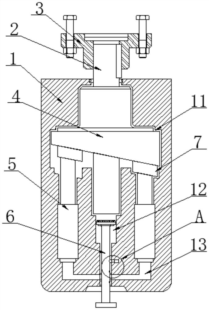
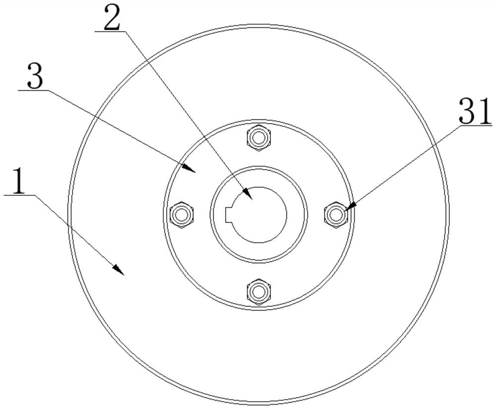
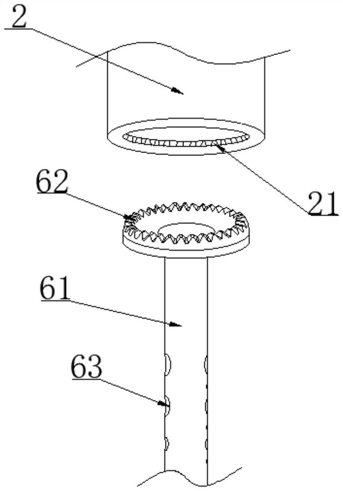
[0030] as attached figure 1 to attach Figure 7 An embodiment of the present invention provides a slow-speed braking mechanism for a high-speed circular knitting machine, which includes a brake case 1, a brake main shaft 2 and a coupling flange 3, and the brake main shaft 2 is rotatably mounted on the brake case 1. Inside, the coupling flange 3 is fixedly sleeved on the top of the brake main shaft 2, and the surface of the coupling flange 3 is provided with a...


PUM


Abstract

The invention discloses a retarding type brake mechanism for a high-speed circular knitting machine, and particularly relates to the field of knitting machines. The retarding type brake mechanism comprises a brake case, a brake main shaft and a connecting shaft flange; the brake main shaft is rotatably mounted in the brake case; a transduction motion cavity, a speed change adjusting cavity and a flow guide pipe cavity are formed in the brake case; an adjusting lock rod assembly is slidably mounted in the speed change adjusting cavity; a hydraulic retarding mechanism is fixedly mounted in the brake case; and the surface of the brake main shaft is fixedly sleeved with an inclined ladder transduction assembly. According to the scheme, the brake mechanism adopts the hydraulic braking principle, and the rotating kinetic energy of the brake main shaft is converted into the hydraulic driving kinetic energy through the abutting motion of the inclined ladder transduction assembly and the hydraulic retarding mechanism, so that the rotating kinetic energy of the inclined ladder transduction assembly is limited through the reaction of the hydraulic limitation; and compared with internal expansion ring type friction braking, the hydraulic braking structure is more stable, and the practicability of the braking structure is improved.

Description

technical field [0001] The invention relates to the technical field of knitting machines, and more specifically, the invention is a slow-speed braking mechanism for high-speed circular knitting machines. Background technique [0002] The warping machine is a device that draws a certain number of warp yarns from the bobbin at the same time to form warp yarn sheets that are uniform and parallel to each other, and winds them on the warp beam or weaving beam in parallel according to the specified length and width. If the yarn breaks during the working process of the warping machine, the operation of the machine must be stopped immediately, which is mainly realized by the braking device. The braking device of the existing warping machine is generally an internal expansion ring type friction braking, and the braking depends on the expansion ring. The friction between the ring extrusion friction plate and the brake disc stops the drum. The brake has small volume, simple structure a...

Claims


Application Information

Patent Timeline
Patent Type & Authority Applications(China)
IPC IPC(8): D04B15/00D04B15/94
CPCD04B15/00D04B15/94Y02P70/62
Inventor 龚财
Owner 杭州奥欣针纺有限公司
Why Eureka
Try Eureka