
Material conveying gas exhaust mechanism and working method thereof

A technology of exhaust mechanism and screw conveyor, which is applied in the direction of conveyor, conveying bulk materials, transportation and packaging, etc., can solve the problems of unachievable gas discharge and inclusion of gas components.

Active Publication Date: 2021-04-30
创志科技(江苏)股份有限公司
View PDF11 Cites 0 Cited by
  • Summary
  • Abstract
  • Description
  • Claims
  • Application Information

AI Technical Summary

Problems solved by technology

[0003] In daily life, a kind of powder needs to be transported. The powder needs to be stirred and mixed in the hot flow gas for transportation. However, the general mixer can only achieve simple transportation effect when combined with the screw conveyor. In the powder transportation, the discharge of gas cannot be realized. Causes gaseous components to be included in the powder transfer

Method used


Image

  • Material conveying gas exhaust mechanism and working method thereof
  • Material conveying gas exhaust mechanism and working method thereof
  • Material conveying gas exhaust mechanism and working method thereof

Examples


Embodiment 1

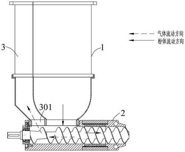
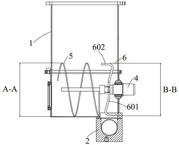
[0028] Such as figure 1 and 2 As shown, a kind of material conveying exhaust mechanism comprises mixing bucket 1 and screw conveyor 2 connected and communicated with the outlet of mixing bucket 1; One side of described mixing bucket 1 is provided with exhaust bin 3, and described The side of the screw conveyor 2 away from the discharge port is provided with an air release port 301, and the exhaust bin 3 is connected and communicated with the air release port 301; wherein the gas-powder mixture stirred by the mixing barrel 1 is separated by the screw conveyor 2 The airflow and powder are formed, the airflow is discharged into the exhaust bin 3 through the air leakage port 301, and the powder is discharged from the discharge port through the screw conveyor 2.

[0029] This kind of material conveying exhaust mechanism has the following beneficial effects: through the setting of the mixing tank 1, the stirring of the powder is promoted; through the setting of the screw conveyor 2...

Embodiment 2

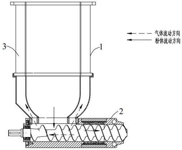
[0041] Such as image 3 As shown, the second embodiment is carried out on the basis of the first embodiment, and the difference between the second embodiment and the first embodiment is that the exhaust bin 3 is arranged around the mixing tank 1, and the gas discharge port 301 is connected to the feeding port of the mixing tank 1 set up.

[0042] The advantage of this scheme is that when the hot air is discharged, part of it will stay in the exhaust chamber 3, and the exhaust chamber 3 is arranged around the mixing bucket 1, thus forming an insulation layer, and the return of the hot air can also It can hinder the discharge of very little entrained powder and ensure its overall good separation and heat preservation effect.

Embodiment 3

[0044] Embodiment three is carried out on the basis of embodiment one.

[0045] A working method of a material conveying exhaust mechanism, the mixing tank 1 stirs the gas-powder mixture and the screw conveyor 2 separates the gas and powder.

[0046] The separated gas is discharged into the exhaust bin 3 along the gas release port 301 ; the separated powder is discharged from the discharge port along the conveying direction of the screw conveyor 2 .

[0047] The working method of the material conveying exhaust mechanism has the following beneficial effects: the stirring effect is good, the powder material is evenly stirred, the quality of the discharged powder is good, and the amount of mixed gas is small.


PUM


Abstract

The invention relates to a material conveying gas exhaust mechanism and a working method thereof. The material conveying gas exhaust mechanism comprises a stirring barrel and a spiral conveyor which is connected and communicated with a discharging port of the stirring barrel; a gas exhaust bin is arranged on one side of the stirring barrel, a gas release opening is formed in the side, away from the discharging port, of the spiral conveyor, and the gas exhaust bin is connected and communicated with the gas release opening; wherein a gas-powder mixture stirred by the stirring barrel is separated by the spiral conveyor to form gas flow and powder, the gas flow is discharged into the gas exhaust bin through the gas release opening, and the powder is discharged from the discharging port through the spiral conveyor; by arranging the stirring barrel, stirring of the powder is facilitated; by arranging the spiral conveyor, powder transportation is facilitated, the whole process is rapid and direct, and operation and monitoring are convenient; and the gas exhaust bin is arranged and cooperates with the gas release port, the gas-powder mixture entering the spiral conveyor is conveniently separated and conveyed, the gas is exhausted along the gas release port and the gas exhaust bin, the whole process is direct and fast, the gas release effect is good, and the quality of discharged powder is high.

Description

technical field [0001] The invention relates to material conveying equipment, in particular to a material conveying exhaust mechanism and a working method thereof. Background technique [0002] Application number: CN201922057685.4 discloses a multifunctional device for preparing sugar beet powder, which has a feeding port, the bottom of the feeding port is provided with a grading bin, and a crushing separator is housed in the grading bin, and the bottom of the grading bin is equipped with There is a filter screen, the outlet of the grading bin is provided with a steam drying tank, the bottom of the steam drying tank is provided with a screen, the outlet of the steam drying tank is provided with a buffer bin, the lower part of the buffer bin is provided with a discharge port, the buffer bin A humidity sensor is provided at the bottom, a conveyor is provided at the outlet of the buffer storehouse, and a multi-stage vibrating screener is provided at the delivery outlet of the c...

Claims


Application Information

Patent Timeline
Patent Type & Authority Applications(China)
IPC IPC(8): B65G53/48B65G53/36
CPCB65G53/48B65G53/36
Inventor 张俊贺辰阳
Owner 创志科技(江苏)股份有限公司
Learn More