Waveshaping reshaping equipment
A waveform shaping and equipment technology, applied in line transmission parts, read/write signal modification, gearbox control/balance, etc., can solve problems such as lack, data smoothing error, unstable jitter, etc. Reduce, data smoothing error reduction, reduce the effect of unstable signals
- Summary
- Abstract
- Description
- Claims
- Application Information
AI Technical Summary
Problems solved by technology
Method used
Image

Examples
Embodiment 1
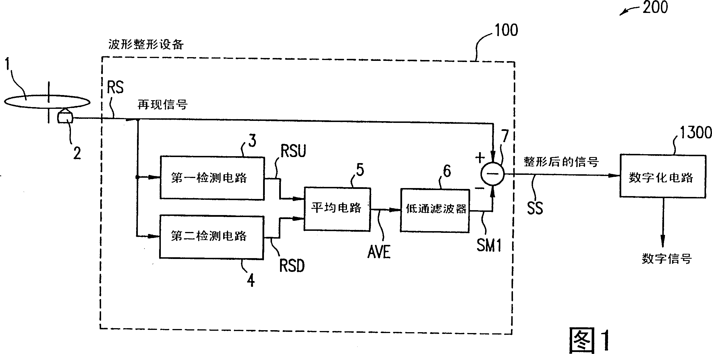
[0063] Shown in FIG. 1 is a block diagram of a reproduction signal processing apparatus 200, showing a reproduction signal processing apparatus 200 in the first embodiment of the present invention. As shown in FIG. 1 , the reproduced signal processing apparatus 200 includes a pulse waveform shaping apparatus 100 and a digital circuit 1300 .
[0064] A signal recorded on the optical disc 1 is reproduced by an optical pickup circuit 2 as a reproduced signal RS.
[0065] The pulse waveform shaping apparatus 100 includes a first detection circuit 3 for detecting a reproduced signal RS reproduced by the optical pickup circuit 2 at a predetermined time constant and detecting an upper envelope RSU, and a second detection circuit 4 for detecting a signal generated by the optical pickup circuit 2. The optical pickup circuit 2 reproduces the reproduced signal RS at a predetermined time constant, and detects a lower envelope RSD, an averaging circuit 5 for finding the average value AVE o...
Embodiment 2
[0080] FIG. 6 is a block diagram describing the structure of a reproduction signal processing apparatus 200A of the second embodiment of the present invention. The parts in the figure that are the same as those in FIG. 1 and have been described above will not be repeated here. The reproduction signal processing apparatus 200A includes a waveform shaping apparatus 100A and a digital circuit 1300 .
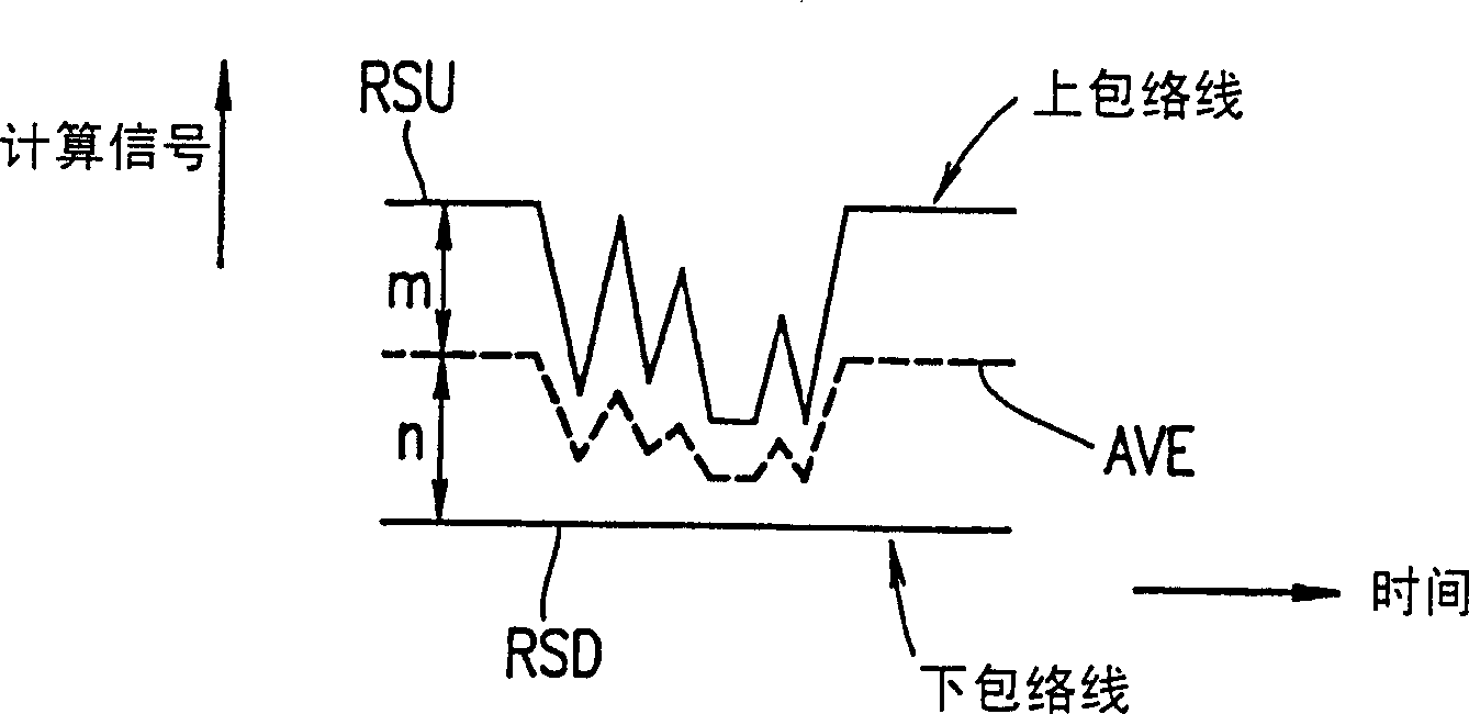
[0081] In addition to the part shown in FIG. 1, the waveform shaping device 100A includes an unbalance detection circuit 8, and the averaging circuit 5 weights the upper envelope RSU and the lower envelope RSD with a weighting coefficient of M:N, thereby calculating The average value AVE is obtained, where the weighting factor is substantially proportional to the unbalanced amount of the reproduced signal RS.
[0082] Unbalance generally occurs under certain disc groove conditions or recording conditions. If a recording pit to be written is larger than a specified standard pit, neg...
Embodiment 3
[0110] FIG. 11 is a block diagram illustrating the structure of a reproduced signal processing apparatus 200B of the third embodiment of the present invention. Parts that appear in the figure that are the same as those in Fig. 1 that have already been described will not be repeated here. The reproduced signal processing device 200B includes a waveform shaping device 100B and a digital circuit 1300 .
[0111] The waveform shaping apparatus 100B includes, in addition to the parts shown in FIG. 1, a drop detection circuit 13 for detecting a dropout indicating a drop in the amplitude of the reproduced signal R.
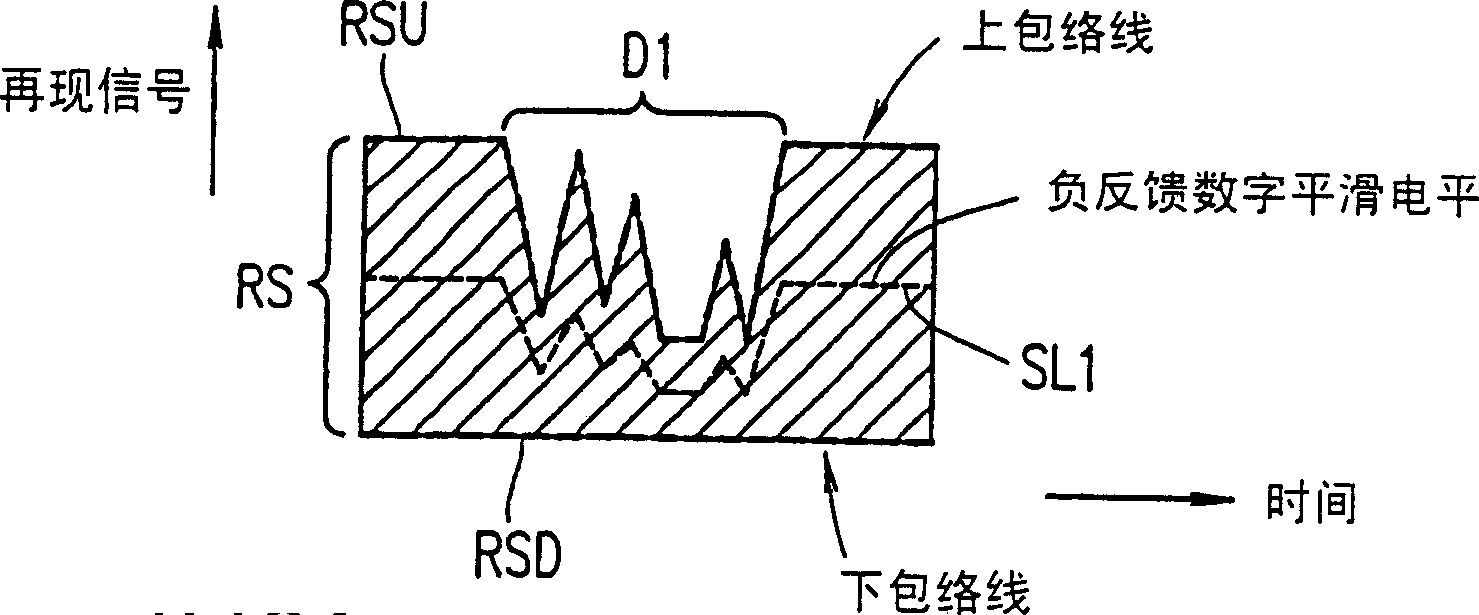
[0112] When the drop detection circuit 13 detects that there is a drop, at least one of the first detection time constant used by the first detection circuit 3 and the second detection time constant used by the second detection circuit 4 is greater than when no drop is detected. The time constant is shorter. When a dip is detected, the negative feedback digital smoothin...
PUM
 Abstract
Description
Claims
Application Information
 - R&D
- Intellectual Property
- Life Sciences
- Materials
- Tech Scout
- Unparalleled Data Quality
- Higher Quality Content
- 60% Fewer Hallucinations
Browse by: Latest US Patents, China's latest patents, Technical Efficacy Thesaurus, Application Domain, Technology Topic, Popular Technical Reports.
© 2025 PatSnap. All rights reserved.Legal|Privacy policy|Modern Slavery Act Transparency Statement|Sitemap|About US| Contact US: help@patsnap.com