
Automatic rust removing, cutting and paint spraying equipment for channel steel

A technology for painting equipment and channel steel, which is applied in painting booths, metal processing equipment, grinding/polishing equipment, etc., and can solve problems such as time-consuming and labor-intensive, increased steel use costs, and low efficiency

Inactive Publication Date: 2021-04-30
俊炜建材(深圳)有限公司
View PDF7 Cites 1 Cited by
  • Summary
  • Abstract
  • Description
  • Claims
  • Application Information

AI Technical Summary

Problems solved by technology

[0002] Channel steel is a long strip of steel with a groove-shaped cross-section. It belongs to carbon structural steel for construction and machinery. It is a section steel with a complex cross-section. Mechanical equipment and vehicle manufacturing, etc. However, due to the increasing amount of steel, many steel can only be stacked outdoors for a long time, causing the steel to gradually rust and affect its use, and for the surface treatment of steel, if it is processed manually, it is time-consuming Force, its inefficiency increases the cost of using steel

Method used


Image

  • Automatic rust removing, cutting and paint spraying equipment for channel steel
  • Automatic rust removing, cutting and paint spraying equipment for channel steel
  • Automatic rust removing, cutting and paint spraying equipment for channel steel

Examples


Embodiment Construction

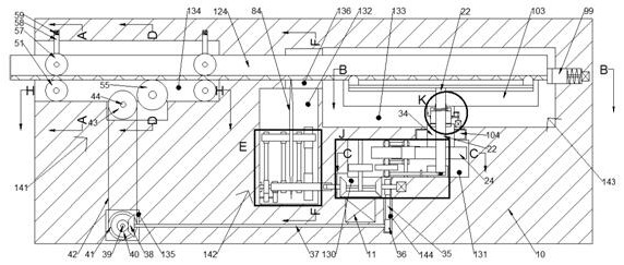
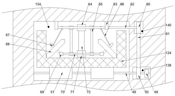
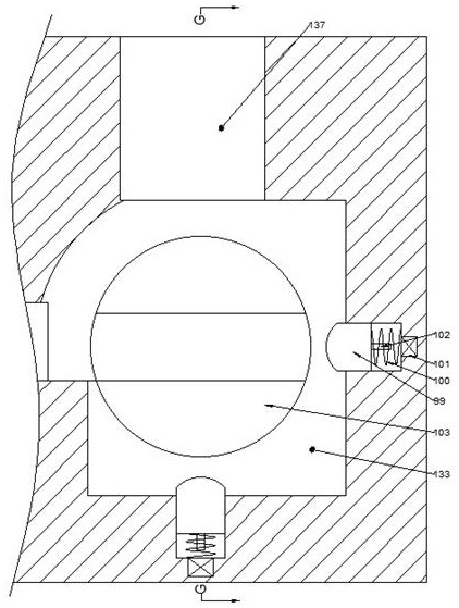
[0028] Combine below Figure 1-11 The present invention is described in detail, wherein, for the convenience of description, the orientations mentioned below are defined as follows: figure 1 The up, down, left, right, front and back directions of the projection relationship itself are the same.

[0029] A channel steel automatic derusting, cutting, and painting equipment of the device of the present invention includes 10, the right side of the body 10 is provided with a steering cavity 133, and the lower side of the steering cavity 133 is provided with an engagement cavity 131, and the engagement cavity 131 is provided with a power chamber 130 on the lower side, and a connecting chamber 144 is provided on the lower side of the power chamber 130. A cutting chamber 132 is provided on the left side of the power chamber 130. A workpiece chamber 136 is provided on the upper side of the cutting chamber 132. The left side of the body 10 is provided with a derusting chamber 134, the ...


PUM


Abstract

The invention discloses automatic rust removing, cutting and paint spraying equipment for channel steel. The equipment comprises a machine body, a steering cavity is formed in the right side of the machine body, a meshing cavity is formed in the lower side of the steering cavity, a power cavity is formed in the lower side of the meshing cavity, a connecting cavity is formed in the lower side of the power cavity, a cutting cavity is formed in the left side of the power cavity, a workpiece cavity is formed in the upper side of the cutting cavity, a rust removing cavity is formed in the left side of the machine body, a transmission cavity is formed in the lower side of the rust removing cavity, a rotating cavity is formed in the front side of the rust removing cavity, an output cavity is formed in the rear side of the steering cavity, a belt wheel cavity is formed in the upper side of the rotating cavity, a bevel gear cavity is formed in the rear side of the rust removing cavity, and a driving cavity and a driven cavity are formed in the lower side of the output cavity; and a rust removing device for conducting complete polishing and rust removing on channel steel is arranged at the rust removing cavity. The equipment can automatically conduct polishing, rust removing, cutting, paint spraying and other treatment procedures on the channel steel, thus, the steel can be conveniently and rapidly treated, subsequent application is facilitated, manual treatment consuming time and labor is not needed, the treatment efficiency of the steel is improved, moreover, the mechanical structures of the equipment are stable, reliable and matched with one another, and multiple functions can be achieved.

Description

technical field [0001] The invention relates to related fields related to building steel structures, in particular to an automatic derusting, cutting and painting equipment for channel steel. Background technique [0002] Channel steel is a long strip of steel with a groove-shaped cross-section. It belongs to carbon structural steel for construction and machinery. It is a section steel with a complex cross-section. Mechanical equipment and vehicle manufacturing, etc. However, due to the increasing amount of steel, many steel can only be stacked outdoors for a long time, causing the steel to gradually rust and affect its use, and for the surface treatment of steel, if it is processed manually, it is time-consuming Force, its inefficiency increases the use cost of steel. Contents of the invention [0003] In order to solve the above problems, the present invention provides an automatic derusting, cutting and painting equipment for channel steel. [0004] The present invent...

Claims


Application Information

Patent Timeline
Patent Type & Authority Applications(China)
IPC IPC(8): B23P23/04B23D79/00B23Q5/04B24B27/033B24B27/00B24B41/00B24B47/12B24B41/04B05B16/20B05B13/02
CPCB23P23/04B23D79/00B23Q5/04B24B27/033B24B27/0076B24B27/0069B24B41/005B24B47/12B24B41/04B05B16/20B05B13/0221B05B13/0278
Inventor 彭俊李
Owner 俊炜建材(深圳)有限公司
Learn More