
Flexible positioning tool unit for railway vehicle

A flexible positioning and rail vehicle technology, applied in auxiliary devices, manufacturing tools, metal processing equipment, etc., can solve the problems of inability to meet batch and diversified production and manufacturing needs, long production change cycle, high processing cost, etc., to achieve Meet the requirements of production beat, simple structure and convenient operation

Pending Publication Date: 2021-04-30
河北京车轨道交通车辆装备有限公司
View PDF0 Cites 0 Cited by
  • Summary
  • Abstract
  • Description
  • Claims
  • Application Information

AI Technical Summary

Problems solved by technology

The tooling has a long replacement cycle, and each time a new positioning block needs to be manufactured, and the processing cost is relatively high
At the same time, the processed positioning block needs to be manually installed on the supporting frame of the tooling, and then the size of the positioning block is repeatedly adjusted using the inspection template, which is labor-intensive and time-consuming
It cannot meet the needs of mass production and diversification

Method used


Image

  • Flexible positioning tool unit for railway vehicle
  • Flexible positioning tool unit for railway vehicle
  • Flexible positioning tool unit for railway vehicle

Examples


Embodiment Construction

[0029] The following will clearly and completely describe the technical solutions in the embodiments of the present invention with reference to the accompanying drawings in the embodiments of the present invention. Obviously, the described embodiments are only some, not all, embodiments of the present invention. Based on the embodiments of the present invention, all other embodiments obtained by persons of ordinary skill in the art without making creative efforts belong to the protection scope of the present invention.

[0030] The purpose of the present invention is to provide a rail vehicle flexible positioning tooling unit, which is used to solve the technical problems in the above-mentioned prior art, and is used to assist in the positioning of rail vehicle body chassis side beams and other long and large components.

[0031] In order to make the above objects, features and advantages of the present invention more comprehensible, the present invention will be further descri...


PUM


Abstract

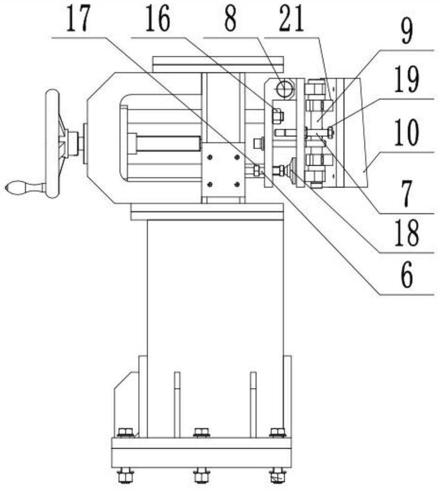
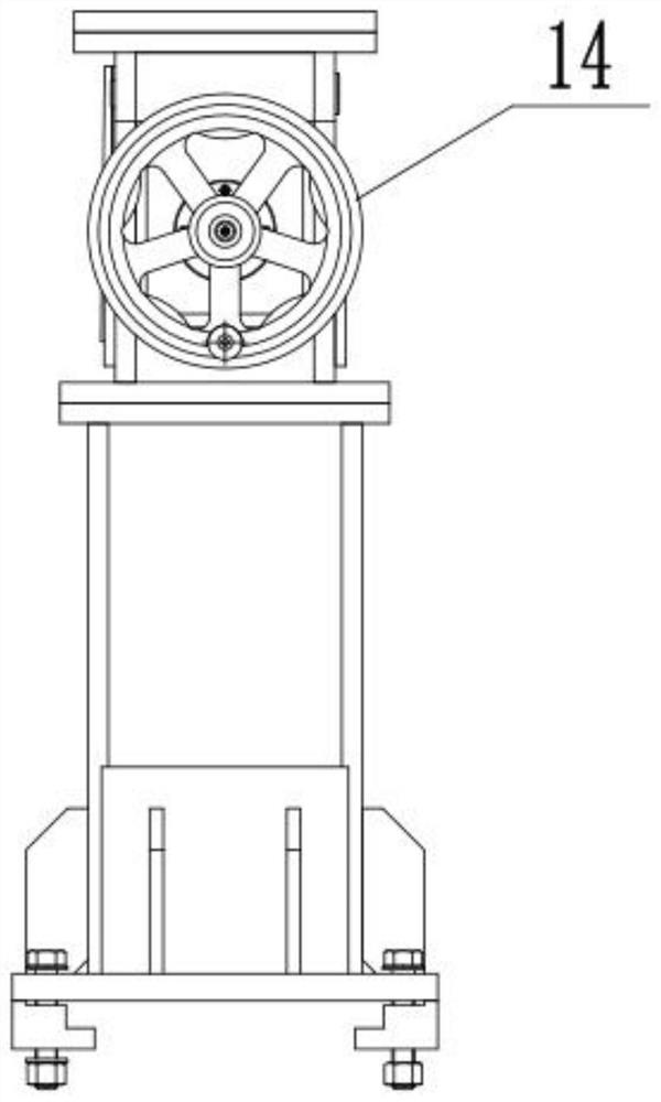
The invention discloses a flexible positioning tool unit for a railway vehicle. The flexible positioning tool unit comprises a supporting frame, a transverse driving device, a transverse transversely-moving plate, a first swing plate, a second swing plate, a first screw and a second screw. The transverse driving device is mounted on the supporting frame; the transverse driving device is used for driving the transverse transversely-moving plate to transversely move in the transverse direction; the first swing plate is rotationally connected with the transverse transversely-moving plate through a first pin shaft; the second swing plate is rotationally connected with the first swing plate through a second pin shaft; the first screw is in threaded connection with the transverse transversely-moving plate, and the end of the first screw directly or indirectly abuts against the first swing plate; and the second screw is in threaded connection with the first swing plate, and the end of the second screw directly or indirectly abuts against the second swing plate. Compared with the prior art, different positioning requirements can be met, rapid production changing is achieved, the period of newly making a positioning block and installing the positioning block of a tool is omitted, and the requirement for the production takt is met.

Description

technical field [0001] The invention relates to the technical field of rail vehicle manufacturing, in particular to a rail vehicle flexible positioning tooling unit. Background technique [0002] For general urban rail vehicles, the car body manufacturing process needs to be completed with the help of some fixtures to assist assembly. With the continuous improvement of domestic and foreign markets for the types and functions of rail vehicles, vehicle manufacturing is also developing towards diversification and diversification. According to the different needs of customers, the structure of the car body has also become diversified, which puts forward higher flexibility requirements for the tooling and fixtures that assist the manufacture of the car body. [0003] The flexible side positioning tooling mechanism in the traditional sense is basically composed of a tooling support frame and a side positioning block (such as Figure 4 As shown), the side positioning block and the...

Claims


Application Information

Patent Timeline
Patent Type & Authority Applications(China)
IPC IPC(8): B23K37/04
CPCB23K37/0443
Inventor 王俊玖尹德猛齐振国李朔晗李充姚肖洁田亚林王崴
Owner 河北京车轨道交通车辆装备有限公司
Learn More