
Hobbing clamp with self-adjustable clamping force for gear hobbing machine tool

A gear hobbing fixture and clamping force technology, applied in the field of gear hobbing, can solve the problems of unstable clamping, difficult to guarantee gear hobbing processing accuracy, affecting the quality of gear hobbing processing, etc., to achieve the effect of improving quality

Active Publication Date: 2021-04-30
深圳市精锋光学五金制品有限公司
View PDF7 Cites 0 Cited by
  • Summary
  • Abstract
  • Description
  • Claims
  • Application Information

AI Technical Summary

Problems solved by technology

[0003] During the gear hobbing process of the gear hobbing machine tool, the workpiece to be processed is placed in the hobbing fixture on the gear hobbing machine tool, and the pull rod on the expansion sleeve is pulled by the hydraulic transmission on the machine tool, and the expansion sleeve on the pull rod is deformed by force It is offset against the inner hole of the gear to complete the clamping and processing of the workpiece. In the process of gear hobbing, with the high-speed rotation of the hob, a large amount of heat energy is generated, and the inner hole of the gear will expand when heated. However, the existing After the stroke position of the pull rod on the gear hobbing machine is set, it cannot be adjusted up and down independently. The inner hole of the gear tooth is heated and expanded, causing a gap between the outer side of the pull rod and the inner hole of the gear tooth after the pull rod is pulled. Unstable clamping may easily cause rolling. Tooth processing accuracy is difficult to guarantee, which further affects the processing quality of gear hobbing

Method used


Image

  • Hobbing clamp with self-adjustable clamping force for gear hobbing machine tool
  • Hobbing clamp with self-adjustable clamping force for gear hobbing machine tool
  • Hobbing clamp with self-adjustable clamping force for gear hobbing machine tool

Examples


Embodiment 1

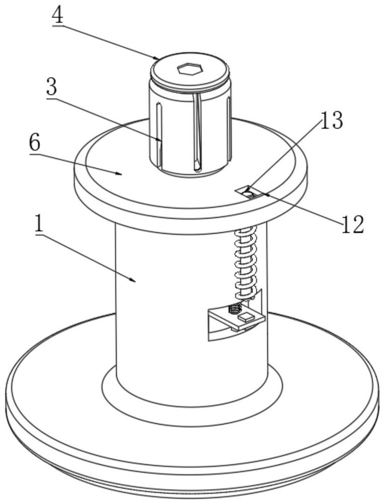
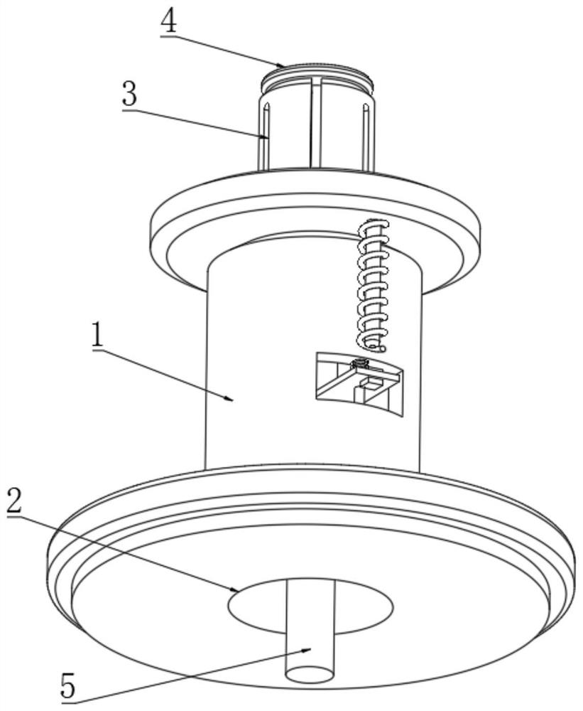
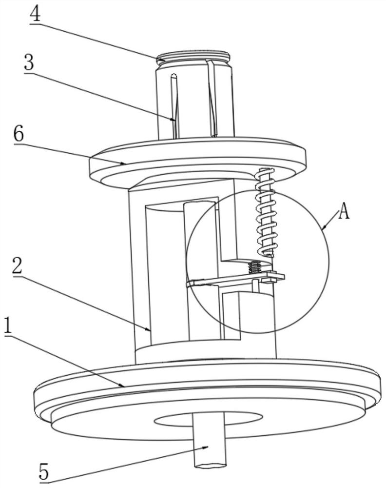
[0024] refer to Figure 1-4 , a gear hobbing fixture with self-adjusting clamping force for gear hobbing machine tools, comprising a fixture body 1, a round hole 2 is opened on the fixture body 1, an expansion sleeve 3 is set on the clamp body 1, and a mounting bracket is placed on the top of the expansion sleeve 3 Plate 4, the bottom side wall of the mounting plate 4 penetrates to the inside of the round hole 2 and is fixedly connected with a tie rod 5, a positioning plate 6 is arranged on the fixture body 1, a square groove 7 is opened on the fixture body 1, and the square groove 7 passes through a guide The device is slidably connected with a transmission plate 8, the guide device is composed of a fixed rod 14 and a spring 15, the fixed rod 14 is fixed on the opposite side wall of the square groove 7, the transmission plate 8 is slidably connected with the side wall of the fixed rod 14, and the spring 15 is sleeved On the side wall of the fixed rod 14, one end of the spring...

Embodiment 2

[0030] A protective plate 16 is installed on the inner wall of the installation groove 12 .

[0031] The material of the protective plate 16 is ceramics.

[0032] refer to Figure 5 , the difference from Embodiment 1 is that: the thermistor 13 on the installation groove 12 is protected by the protective plate 16, so as to avoid damage to the thermistor 13 during the processing of the teeth, and the setting of the ceramic material , while insulating, the efficiency of heat conduction is increased, and the sensitivity of clamping force self-regulation is further increased.


PUM


Abstract

The invention discloses a hobbing clamp with self-adjustable clamping force for a gear hobbing machine tool. The clamp comprises a clamp body, wherein a circular hole is formed in the clamp body, the clamp body is sleeved with an expansion sleeve, a mounting plate is placed at the top of the expansion sleeve, a pull rod penetrates through the side wall of the bottom of the mounting plate to the interior of the circular hole and is fixedly connected to the side wall of the bottom of the mounting plate, and a positioning plate is arranged on the clamp body; a square slot is formed in the clamp body, a transmission plate is slidably connected to the square slot through a guide device, the transmission plate is rotatably connected to the side wall of the pull rod, and a magnet is fixedly connected to the side wall of the end, away from the pull rod, of the transmission plate. The invention relates to the technical field of hobbing, and aims to realize automatic adjustment of the clamping force of the hobbing clamp, prevent the hobbing clamp from not clamping a disc gear workpiece in place due to over-high temperature and improve the hobbing quality.

Description

technical field [0001] The invention relates to the technical field of gear hobbing, in particular to a gear hobbing fixture with self-adjusting clamping force for a gear hobbing machine tool. Background technique [0002] Gear hobbing machine is the most widely used machine tool among gear processing machine tools. It can cut straight and helical cylindrical gears, and can also process worm gears and sprockets. A gear processing machine tool for processing straight, helical and herringbone cylindrical gears and worm gears with a hob according to the generation method. When this kind of machine tool uses a special hob, it can also process various special tooth-shaped workpieces such as splines and sprockets. [0003] During the gear hobbing process of the gear hobbing machine tool, the workpiece to be processed is placed in the hobbing fixture on the gear hobbing machine tool, and the pull rod on the expansion sleeve is pulled by the hydraulic transmission on the machine to...

Claims


Application Information

Patent Timeline
Patent Type & Authority Applications(China)
IPC IPC(8): B23F23/06
CPCB23F23/06
Inventor 廖冬生
Owner 深圳市精锋光学五金制品有限公司
Learn More