Rotary rhombic wire mesh demisting method and device

A technology of a defogging device and a wire mesh demister, which is applied in the field of a rotary diamond wire mesh defogging method and device, can solve the problems of poor demisting effect of fine droplets, difficulty in removing fine droplets, and inability to flush in all directions. , to achieve the effect of improving the efficiency of mist removal and dust removal, small resistance, and uniform distribution of flue gas.

Pending Publication Date: 2021-04-30
SOUTH CHINA UNIV OF TECH +1
View PDF0 Cites 4 Cited by
  • Summary
  • Abstract
  • Description
  • Claims
  • Application Information

AI Technical Summary

Problems solved by technology

The baffle type demister uses the collision between the liquid droplets and the solid surface to condense and separate the droplets, and it is difficult to remove the fine droplets in the flue gas
The swirling plate demister uses the swirl centrifugal force generated when the flue gas flows to separate the liquid droplets from the solid particles, but it is greatly affected by the flue gas flow rate, and it is difficult to remove the fine liquid droplets in the flue gas; the tube type demister passes through Inertial collision and direct interception achieve the purpose of defogging, and the effect of removing droplets with a particle size of more than 400 μm is remarkable, but the defogging effect for fine droplets is still not good; conventional screen demisters use multi-layer screens. Although the dust removal effect is good, the structure is fixed, it cannot be washed in all directions, it is easy to block, the running resistance is large, it cannot meet the requirements of variable working conditions, and the secondary carry is serious

Method used


Image

  • Rotary rhombic wire mesh demisting method and device
  • Rotary rhombic wire mesh demisting method and device

Examples


Embodiment

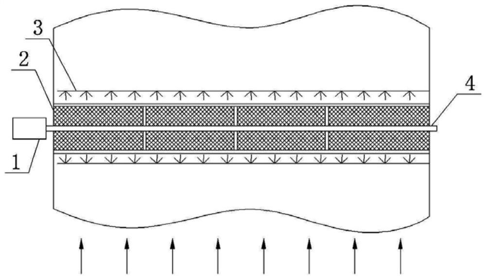
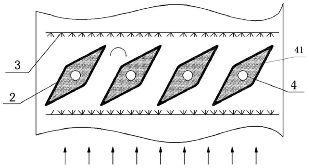
[0032] like Figure 1-2 shown. The invention discloses a rotating rhombic wire mesh defogging device, which comprises a defogging system and a flushing water system arranged on the top of a desulfurization tower.

[0033] The demisting system is formed by a plurality of rhombic wire mesh demisters 2, and they are arrayed and distributed on the flue gas outlet flue at the top of the desulfurization tower;

[0034] Each diamond-shaped wire mesh eliminator 2 is supported by a rotating shaft 4, and they are arranged in a staggered array;

[0035] The diamond-shaped wire mesh eliminator 2 arranged on the same rotating shaft 4 overlaps and rotates with the diamond-shaped wire mesh eliminator 2 on another rotating shaft 4, so that the distance between each group of diamond-shaped wire mesh eliminators 2 Relatively adjustable tilt angle;

[0036] When the desulfurized flue gas flows through the rhombic wire mesh demister 2, the liquid droplets and particles carried in the flue gas ...


PUM

PropertyMeasurementUnit
Diameteraaaaaaaaaa

Abstract

The invention discloses a rotary rhombic wire mesh demisting method and a rotary rhombic wire mesh demisting device. The rotary rhombic wire mesh demisting device comprises a rhombic wire mesh demisting system arranged at the top of a desulfurizing tower and an automatic rotary control system. When flue gas flows into the lower layer of the rhombus-shaped wire mesh demister, droplets and other fine particles carried in the flue gas are intercepted by a wire mesh in the rhombus-shaped wire mesh demister, the droplets and the large particles are subjected to inertial separation, the small particles are subjected to coagulation, sedimentation and separation, and the flue gas subjected to preliminary demisting of the lower layer of wire mesh enters the upper layer of wire mesh again and then is demisted and dedusted. According to the device, the wire mesh demister is rotationally combined with the connecting rod, so that the device has the characteristics of efficient demisting and dedusting, uniform flue gas distribution, energy conservation, adaptability to different working condition changes and the like, can effectively solve the problems of poor working condition applicability, large resistance, easiness in scaling and easiness in blockage of the traditional demister, and can effectively reduce the formation of gypsum rain and the secondary carrying of flue gas.

Description

technical field [0001] The invention relates to a demister in a chemical process, in particular to a method and device for demistering a rotating rhombus wire mesh. Background technique [0002] At present, most of the desulfurization systems in thermal power plants use wet limestone / gypsum flue gas desulfurization systems. Among them, the mist eliminator is an important equipment in the wet limestone / gypsum flue gas desulfurization system. The mist eliminator is used to remove a large number of small droplets carried in the wet flue gas after desulfurization, so as to avoid the formation of gypsum scale and equipment pollution caused by downstream equipment. , clogging and corrosion. If the wet discharge process is adopted, when the performance of the demister is not good, it is easy to cause "gypsum rain" and pollute the environment around the power plant. Optimizing the traditional flue gas desulfurization operation process and improving the efficiency of desulfurizatio...

Claims


Application Information

Patent Timeline
IPC IPC(8): B01D50/00B01D45/08B01D46/00B01D46/10B01D46/44B01D51/02
CPCB01D45/08B01D46/10B01D46/0036B01D46/444B01D46/446B01D46/442B01D46/44B01D51/02B01D2247/10B01D2247/107B01D2247/105B01D46/56B01D46/681B01D50/20
Inventor 刘定平谢红夏松马佩佩
Owner SOUTH CHINA UNIV OF TECH
Why Eureka
Try Eureka