Converging and guiding device for tube bundle dedusting and demisting
A technology of diversion device and diversion ring, which is applied to the separation of dispersed particles, chemical instruments and methods, and separation methods. Eliminate the secondary entrainment of drops and other problems, and achieve the effects of liquid separation, good effect of dust removal and fog removal, and improved effect of dust removal and fog removal
- Summary
- Abstract
- Description
- Claims
- Application Information
AI Technical Summary
Problems solved by technology
Method used
Image

Examples
Embodiment approach 1
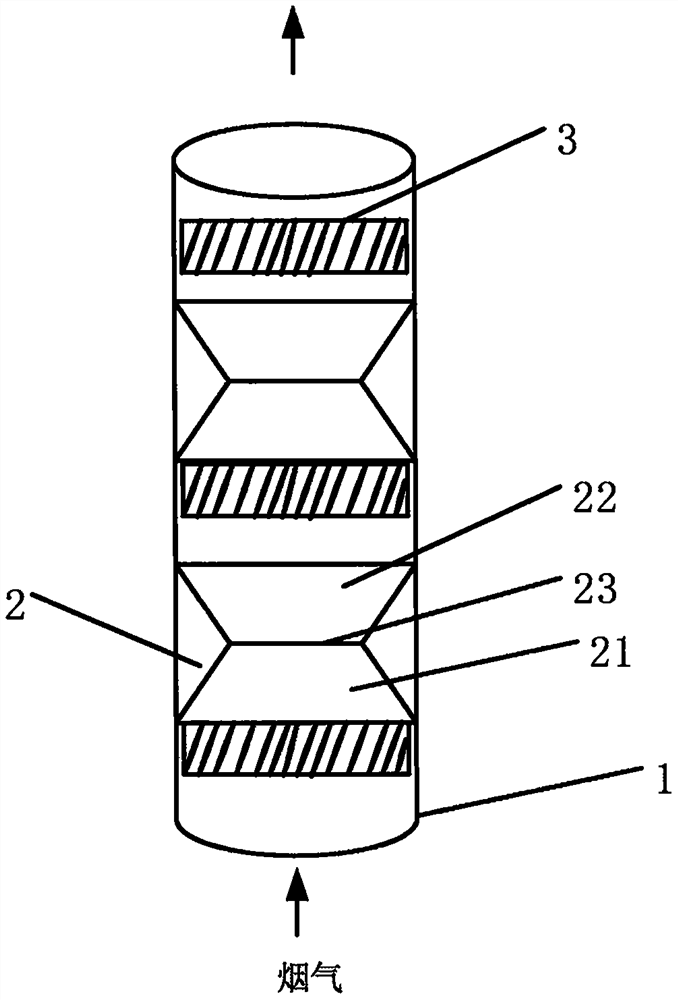
[0041] figure 2 It is a structural schematic diagram of a three-stage cyclone tube bundle dedusting and demisting cylinder structure and related confluence and diversion devices according to Embodiment 1 of the present invention.
[0042] Such as figure 2 As shown, a tube bundle cylinder 1 with openings at both ends, hollow, opening diameter D=400mm, and wall thickness 0.5cm is arranged coaxially and spaced from the bottom to the top. device, confluence diversion device 2, three-stage cyclone. The confluence and diversion device 2 is installed above the swirler 3 and is directly connected to the end face of the swirler collar.
[0043] Such as figure 2 As shown, the diversion and diversion device 2 is a hollow cylinder with openings at both ends, a reduced diameter in the middle, and a smooth inner wall. It includes a diversion ring 21, a diversion ring 22 and a speed increaser 23, and is prepared by integral molding. In this embodiment, the speed increaser 23 is a stra...
Embodiment approach 2
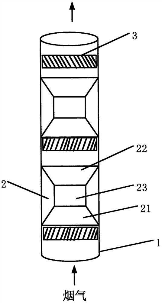
[0047] image 3 It is a structural schematic diagram of a three-stage cyclone tube bundle dust and mist removal cylinder and confluence and diversion device according to Embodiment 2 of the present invention. Compared with Embodiment 1, the difference of this embodiment is mainly in the structure of the diversion and diversion device 2 .
[0048] Such as image 3 As shown, the diversion ring 21 and the diversion ring 22 are asymmetric structures with respect to the speed increaser 23, the speed increaser 23 is set as a Venturi type speed increase ring with a height of 100mm, and the diversion ring 22 and the diversion ring 21 are designed asymmetrically of funnel shape. The diameter of the upper opening of the speed increasing ring is smaller than the diameter of the lower opening of the speed increasing ring. Same diameter.
[0049] Expanding the speed increaser to a 100mm Venturi type speed increase ring, in addition to better shaping the passing airflow, it can also fur...
Embodiment approach 3
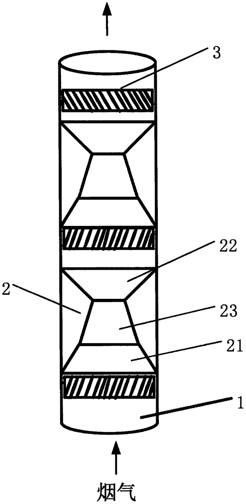
[0051] Figure 4-6 It shows the structure and partially enlarged schematic diagram of a confluence and diversion device for a tube bundle dust removal and mist removal cylinder according to Embodiment 3 of the present invention. Compared with Embodiment 2, the difference of this embodiment is mainly in the structure of the confluence and diversion device 2 .
[0052] First, if Figure 4 As shown, on the inner wall of the guide ring 22, three bar-shaped guide grooves 223 are arranged evenly and at equal intervals, as Figure 5 As shown, the depth of the diversion groove is 2mm, and the cross section of the diversion groove is arc-shaped, such as Figure 6 As shown, the guide groove 223 extends from the guide ring outlet 222 on the inner wall of the guide ring 22 to the guide ring inlet 221, and continues downward along the inner wall of the diversion flow guide device 2 through the inner wall of the speed-increasing ring, The outlet port 212 of the bus ring 21 extends to the...
PUM
| Property | Measurement | Unit |
|---|---|---|
| height | aaaaa | aaaaa |
Abstract
Description
Claims
Application Information
 - R&D
- Intellectual Property
- Life Sciences
- Materials
- Tech Scout
- Unparalleled Data Quality
- Higher Quality Content
- 60% Fewer Hallucinations
Browse by: Latest US Patents, China's latest patents, Technical Efficacy Thesaurus, Application Domain, Technology Topic, Popular Technical Reports.
© 2025 PatSnap. All rights reserved.Legal|Privacy policy|Modern Slavery Act Transparency Statement|Sitemap|About US| Contact US: help@patsnap.com