Novel composite wet-type dedusting and demisting tower

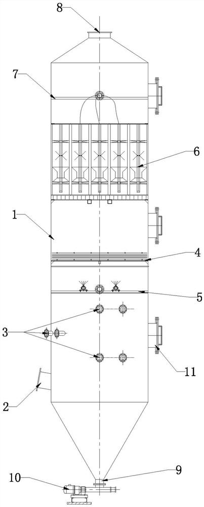
A technology of wet dust removal and demisting tower, applied in combination device, separation method, separation of dispersed particles, etc., can solve the problem that wet exhaust gas containing fine dust cannot be effectively dedusted and demisted, and the content of mist droplets in outlet exhaust gas cannot be controlled and cannot be controlled. It is suitable for problems such as wet exhaust gas, and achieves the effect of good removal effect, improved dust removal and demisting ability, and small footprint.

Pending Publication Date: 2021-10-08
BEIJING GUODIAN LONGYUAN ENVIRONMENTAL ENG
View PDF10 Cites 0 Cited by
  • Summary
  • Abstract
  • Description
  • Claims
  • Application Information

AI Technical Summary

Problems solved by technology

The filter dust collector makes the dust-laden air flow pass through the filter material to separate and capture the dust particles. It is divided into two methods: internal filtration and surface filtration. The dust removal efficiency is generally 90%~99%, but it is not suitable for high temperature or humidity containing droplets. exhaust gas
The dust collector uses liquid to wash the dusty gas, so that the dust particles collide with the liquid droplets or liquid film to be captured and separated from the air flow. The dust removal efficiency is 80%~95%, but the content of the outlet exhaust gas mist cannot be controlled, and the operating cost is relatively high. high
At present, various single types of dust collectors cannot effectively remove dust and fog from wet waste gas containing fine dust. How to effectively treat wet waste gas containing fine dust has become a key problem that needs to be solved urgently

Method used


Image

  • Novel composite wet-type dedusting and demisting tower
  • Novel composite wet-type dedusting and demisting tower
  • Novel composite wet-type dedusting and demisting tower

Examples


Embodiment Construction

[0024] Hereinafter, an embodiment of a novel composite wet dedusting and demisting tower of the present invention will be described with reference to the accompanying drawings. The examples described here are specific specific implementations of the present invention, and are used to illustrate the concept of the present invention. They are all explanatory and exemplary, and should not be construed as limiting the implementation of the present invention and the scope of the present invention. In addition to the embodiments described here, those skilled in the art can also adopt other obvious technical solutions based on the claims of the application and the contents disclosed in the description, and these technical solutions include adopting any obvious changes made to the embodiments described here. Replacement and modified technical solutions.

[0025] In the description of the present invention, it should be noted that the orientations or positional relationships indicated ...


PUM


Abstract

The invention discloses a novel composite wet-type dedusting and demisting tower which comprises a purification tower, the purification tower is vertically arranged, a cyclone dedusting area, a spraying dedusting area, a liquid drop settling area, a rectification area, a gas-liquid separation area and a flow stabilization area are sequentially arranged in a tower body of the purification tower from bottom to top, the cyclone dedusting area is of an inverted-cone-shaped structure, a waste gas inlet tangent to the cyclone dedusting area is formed in the top of the cyclone dedusting area, a mud bin is formed in the bottom of the cyclone dedusting area, a mud outlet is formed in the bottom of the mud bin, and a screw pump is installed at the mud outlet in a sealed mode for negative-pressure mud discharging. The tower is simple in structure and small in occupied area, dust particles and fog drops in waste gas are gradually separated and purified step by step through the cyclone dedusting area, the spraying dedusting area and the gas-liquid separation area in sequence from bottom to top in the waste gas flowing direction, and the fine dust particle removal effect is good. By arrangement of the rectification area, the liquid drop settling area and the flow stabilization area, the dedusting and demisting capability of the purification tower on wet waste gas containing fine dust is further improved, and the purposes of reducing cost and improving efficiency are achieved.

Description

technical field [0001] The invention relates to the technical field of dust removal and fog removal, in particular to a novel composite wet dust removal and fog removal tower. Background technique [0002] According to the collection mechanism, dust collectors can be divided into mechanical dust collectors, electric dust collectors, filter dust collectors and washing dust collectors. The mechanical dust collector relies on mechanical force to remove dust particles from the airflow. It has a simple structure, low equipment and operating costs, but the dust removal efficiency, especially for fine dust, is not high. The electrostatic precipitator uses electrostatic force to separate the dust particles from the air flow. It is often classified according to the plate type and the tube type. It is characterized by small air flow resistance and a dust removal efficiency of over 99%. The investment is higher and the floor area is larger. The filter dust collector makes the dust-la...

Claims


Application Information

Patent Timeline
Patent Type & Authority Applications(China)
IPC IPC(8): B01D50/00
Inventor 孙明明李明明常少英王丽波伊然赵雅萱
Owner BEIJING GUODIAN LONGYUAN ENVIRONMENTAL ENG
Why Eureka
Try Eureka