
Distributed direct two-way coupling method for earth surface and pipe network

A two-way coupling and distributed technology, applied in the sewer system, waterway system, special data processing applications, etc., can solve the problems that the surface and the pipe network are not suitable for areas with insufficient pipe network data, and there is no distinction between different functions.

Active Publication Date: 2021-04-27
CHINA INST OF WATER RESOURCES & HYDROPOWER RES
View PDF7 Cites 4 Cited by
  • Summary
  • Abstract
  • Description
  • Claims
  • Application Information

AI Technical Summary

Problems solved by technology

The shortcoming of the coupling method between the ground surface and the pipe network shown in this article is that it does not distinguish the different functions of the inspection well and the rainwater grate in the actual drainage pipe network system. In fact, the inspection wells in the urban drainage system are covered by cover plates. , not in an open state, the water exchange between the surface and the drainage pipe network is mainly done through the rainwater grate, and the rainwater grate and the inspection well must be treated separately
In addition, the coupling method between the surface and the pipeline network shown in this article is not suitable for areas with insufficient pipeline network data

Method used


Image

  • Distributed direct two-way coupling method for earth surface and pipe network
  • Distributed direct two-way coupling method for earth surface and pipe network
  • Distributed direct two-way coupling method for earth surface and pipe network

Examples


Embodiment 1

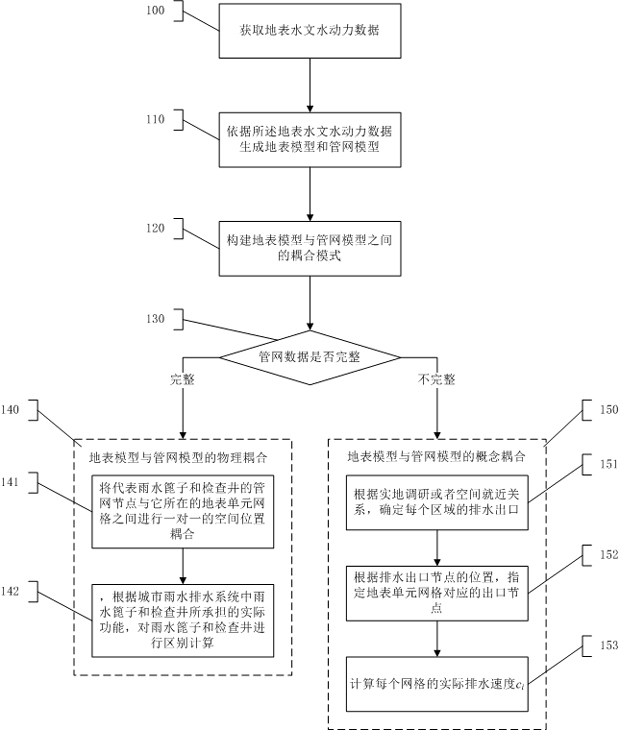
[0052] Such as figure 1 As shown, step 100 is executed to acquire surface hydrological and hydrodynamic data. The surface hydrological and hydrodynamic data include surface water depth, surface velocity, rainfall intensity, infiltration intensity, drainage intensity, frictional resistance, pipeline flow area, pipeline internal flow, pipeline internal velocity, water head and hydraulic radius.

[0053] Step 110 is executed to generate a surface model and a pipe network model according to the surface hydrological and hydrodynamic data. The surface model is a surface distributed hydrological and hydrodynamic model. Based on the distributed hydrological and hydrodynamic model of the surface, the rainfall production and confluence and surface water accumulation are all calculated based on the same surface grid, and the calculation formula is:

[0054]

[0055]

[0056]

[0057] in, is the partial differential sign, t it's time h is the water depth, u and v yes x ...

Embodiment 2

[0076] The present invention proposes a new direct two-way coupling mode, that is, the coupling mode of Rainfall-Overland-Sewer, hereinafter referred to as ROS mode. In this mode, the surface adopts a distributed hydrological and hydrodynamic model, and the rainfall directly acts on the surface grid, and the calculation of rainfall generation, confluence and water inundation is based on the unified surface grid, and the surface model and the pipe network model perform two-way coupling. This model conforms to the actual physical process of water accumulation caused by urban rainfall, so it can more reasonably simulate the surface flooding process caused by urban rainstorms.

[0077] In the ROS model, firstly, the surface model adopts a distributed hydrological and hydrodynamic model, as shown in formulas (1), (2) and (3). This is the basis for the direct two-way coupling between the surface model and the pipe network model. Based on the distributed hydrological and hydrodynam...

Embodiment 3

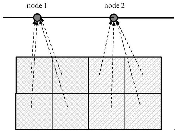
[0096] The distribution of the surface model and pipe network model of a certain urban area is shown as Figure 4 As shown, the pipe network data on the main road is detailed, the rainwater grates and inspection wells are classified and the connection relationship is clear and reliable. However, the internal pipe network data of the community other than the main road are missing. According to the existing pipe network data, the surface grid units on the main roads, and the rainwater grates and inspection wells of the drainage pipe network are constructed according to the positional relationship to establish a one-to-one physical coupling relationship. For the surface grid units of residential areas and buildings, the drainage outlets of the grid units are allocated according to the spatial proximity relationship, such as Figure 5 As shown, the number marked on each surface grid unit represents the drainage outlet of the unit grid, that is, the number of the inspection well. ...


PUM


Abstract

The invention provides an earth surface and pipe network distributed direct two-way coupling method, which comprises the steps of collecting hydrodynamic data of surface hydrology, and further comprises the following steps: generating an earth surface model and a pipe network model according to the hydrodynamic data of the surface hydrology, the earth surface model being an earth surface distributed hydrodynamic model; and on the basis of the surface model and the pipe network model, a coupling mode between the surface model and the pipe network model is constructed according to the actual composition of the urban drainage pipe network and the data coverage situation, and the coupling mode at least comprises physical coupling and concept coupling. The invention provides a novel distributed direct two-way coupling mode, namely a coupling mode of rainfall-earth surface-pipe network (Sewer), under the mode, the earth surface adopts a distributed hydrodynamic model, rainfall directly acts on earth surface grids, rainfall runoff generation and confluence and accumulated water flooding are calculated based on the unified earth surface grids, and therefore, the accuracy of the rainfall runoff generation and confluence and accumulated water flooding can be improved. Meanwhile, the surface model and the pipe network model are bidirectionally coupled.

Description

technical field [0001] The invention relates to the technical field of municipal engineering, in particular to a distributed direct two-way coupling method between the ground surface and a pipe network. Background technique [0002] In the process of urban storm flood simulation, the coupled calculation of the surface model and the pipe network model has always been one of the key points and technical difficulties. The existing urban storm flood simulation model mainly adopts the model of Rainfall-Catchment-Sewer-Overland (hereinafter referred to as RCSO). According to this model, the sub-basin must be divided according to the position of the inspection well in the drainage pipe network system, and then the rainfall directly acts on the sub-basin, and then the sub-basin rainfall production and flow model is used to calculate the yield of the sub-basin. The production flow is directly added to the pipeline network model through the inspection well. When the pipe network ins...

Claims


Application Information

Patent Timeline
IPC IPC(8): G06F30/18G06F30/20E03F1/00E03F3/02
CPCE03F1/00E03F3/02G06F30/18G06F30/20
Inventor 张红萍胡昌伟郑敬伟李敏臧文斌刘媛媛刘业森李匡徐美柴福鑫万洪涛刘舒
Owner CHINA INST OF WATER RESOURCES & HYDROPOWER RES
Learn More