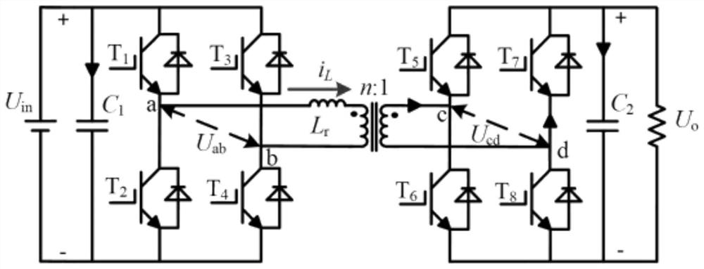
Open-circuit fault diagnosis method for dual-active-bridge DC-DC converter
A technology of DC-DC and dual active bridges, applied in the direction of fault location, etc., can solve the problems of unable to locate the fault switch, unable to popularize and apply dual active bridge DC-DC converters, and more detection information
- Summary
- Abstract
- Description
- Claims
- Application Information
AI Technical Summary
Problems solved by technology
Method used
Image
Examples
Embodiment
[0056] Embodiment: the Matlab / Simulink version used is 2014b, the control period is 20us, and the control mode is unified phase shift (unified phase shift, UPS) control.
[0057] Step 1: Build a normal working model of a dual active bridge DC-DC converter on Matlab / Simulink, set the PWM switching frequency to 1000Hz, input DC voltage to 3000V, output reference voltage to 3000V, auxiliary inductance to 1.8mH, and load resistance to 20Ω; Build the system UPS control algorithm in Simulink to realize the normal operation of the dual active bridge DC-DC converter, and embed the fault diagnosis algorithm in it for online fault monitoring;
[0058] Step 2: By setting the loss of the driving signal sent by the control system, the effect of simulating the open circuit failure of the switch tube is simulated;
[0059] Step 3: Every other control cycle, sample the primary side input voltage U in , Secondary side output voltage U o , primary side inductor current i L , Voltage between ...
PUM
 Abstract
Description
Claims
Application Information
 - Generate Ideas
- Intellectual Property
- Life Sciences
- Materials
- Tech Scout
- Unparalleled Data Quality
- Higher Quality Content
- 60% Fewer Hallucinations
Browse by: Latest US Patents, China's latest patents, Technical Efficacy Thesaurus, Application Domain, Technology Topic, Popular Technical Reports.
© 2025 PatSnap. All rights reserved.Legal|Privacy policy|Modern Slavery Act Transparency Statement|Sitemap|About US| Contact US: help@patsnap.com


