A motor rotor shaft sleeve assembly machine

A technology of motor rotor shaft and motor rotor, which is applied in the manufacture of stator/rotor body, etc., can solve the problems of low production efficiency, inability to ensure that the shaft sleeve is in place, and cannot meet the simultaneous pressing of two axes, and achieve low cost, simple structure, and prevent The effect of crushing the bushing

Active Publication Date: 2021-12-10
HANGZHOU WEIGUANG ELECTRONICS
View PDF5 Cites 0 Cited by
  • Summary
  • Abstract
  • Description
  • Claims
  • Application Information

AI Technical Summary

Problems solved by technology

[0003] The invention solves the problems of the prior art that using the bushing clamp to press the bushing can not ensure that the bushing is in place and is only suitable for pressing one shaft, which cannot meet the simultaneous pressing of two shafts, and the production efficiency is low. It proposes a motor rotor shaft The sleeve assembly machine divides the sleeve pressing process into two steps, which are sleeve insertion and press-in, instead of using the sleeve clamp to directly press the sleeve to ensure that the sleeve sleeve is in place, and can simultaneously carry out two shafts of the motor rotor. Press to improve production efficiency

Method used


Image

  • A motor rotor shaft sleeve assembly machine
  • A motor rotor shaft sleeve assembly machine
  • A motor rotor shaft sleeve assembly machine

Examples


Embodiment

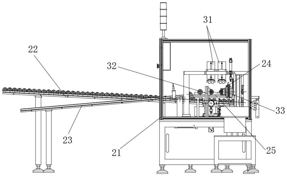
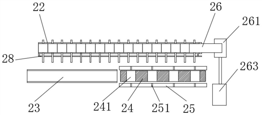
[0039] This embodiment proposes a motor rotor shaft sleeve assembly machine, refer to figure 1 Including the frame 21, the motor rotor positioning block 24 is fixed on the frame 21, the two sides of the motor rotor positioning block 24 are symmetrically provided with a shaft sleeve inserting device 33 and a shaft sleeve pressing device 32, and the motor rotor positioning block 24 is provided with a motor rotor Compression block 31, the motor rotor compression block 31 is used to compress the motor rotor positioned on the motor rotor positioning block 24, and the shaft sleeve inserting device 33 is used to grab the shaft sleeve and initially insert the shaft sleeve into the shaft of the motor rotor , the sleeve press-in device 32 is used to press the initially inserted sleeve to a designated position, the frame 21 is also provided with a motor rotor transmission device and a motor rotor sleeve option device, and the motor rotor transmission device is used for motor rotor transm...


PUM


Abstract

The invention proposes a motor rotor shaft sleeve assembly machine, which includes a frame on which a motor rotor positioning block is fixed. Both sides of the motor rotor positioning block are symmetrically provided with a shaft sleeve inserting device and a shaft sleeve pressing device. A motor rotor pressing block is arranged above the motor rotor positioning block, the motor rotor pressing block is used to press the motor rotor positioned on the motor rotor positioning block, and the shaft sleeve inserting device is used to grab the shaft sleeve and hold the shaft The sleeve is preliminarily inserted on the shaft of the motor rotor, and the sleeve pressing device is used to press the initially inserted sleeve to a designated position. The invention divides the pressing-in process of the bushing into two steps, respectively inserting and pressing in, replacing the direct pressing of the bushing by the bushing clamp, ensuring that the bushing is in place, and simultaneously pressing the two shafts of the motor rotor, Increase productivity.

Description

technical field [0001] The invention relates to the technical field of motor rotors, in particular to a motor rotor shaft sleeve assembly machine. Background technique [0002] Referring to the Chinese patent CN201920615857.2, an automatic motor rotor bushing press-in device includes an operating table, a controller, a bushing vibration plate, a bushing guide rail, a bushing press-in assembly, a gasket press-in assembly, and a snap-in press-in Assembly and rotor guide rail, the sleeve guide rail is arranged in front of the shaft sleeve vibration plate, the other end of the sleeve guide rail is provided with a sleeve press-in assembly, the rotor guide rail is arranged in front of the shaft sleeve guide rail, the gasket The press-in assembly is arranged on one side of the rotor guide rail, two gasket press-in assemblies are arranged side by side, and the snap-in press-in assembly is arranged on the left side of the gasket press-in assembly; the sleeve press-in assembly include...

Claims


Application Information

Patent Timeline
Patent Type & Authority Patents(China)
IPC IPC(8): H02K15/02
CPCH02K15/02
Inventor 李磊谢盼盼蒋凯张媛沈国平
Owner HANGZHOU WEIGUANG ELECTRONICS
Why Eureka
Try Eureka