Eureka AIR delivers breakthrough ideas for toughest innovation challenges, trusted by R&D personnel around the world.

Fluid compensation type air conditioning system, control method, computer equipment and terminal

An air-conditioning system and control method technology, which is applied in the field of computer equipment and terminals, and liquid-replenishing air-conditioning systems, and can solve problems such as low heat exchange capacity and energy efficiency, small aperture, and high dryness

Active Publication Date: 2021-04-20
GREE ELECTRIC APPLIANCES INC
View PDF5 Cites 1 Cited by
  • Summary
  • Abstract
  • Description
  • Claims
  • Application Information

AI Technical Summary

Problems solved by technology

[0004] (1) In the heating mode, due to the small diameter of the microchannel heat exchanger and the long process, the refrigerant often has a high dryness in the last process, that is, the overheating is serious, resulting in low heat exchange capacity and energy efficiency The problem
[0005] (2) To solve the problem of poor heating comfort due to the small aperture of the outdoor micro-channel heat exchanger and the long process flow, which is easy to frost in the heating mode

Method used


Image

  • Fluid compensation type air conditioning system, control method, computer equipment and terminal
  • Fluid compensation type air conditioning system, control method, computer equipment and terminal
  • Fluid compensation type air conditioning system, control method, computer equipment and terminal

Examples


Embodiment 1

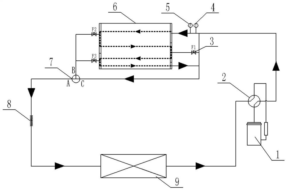
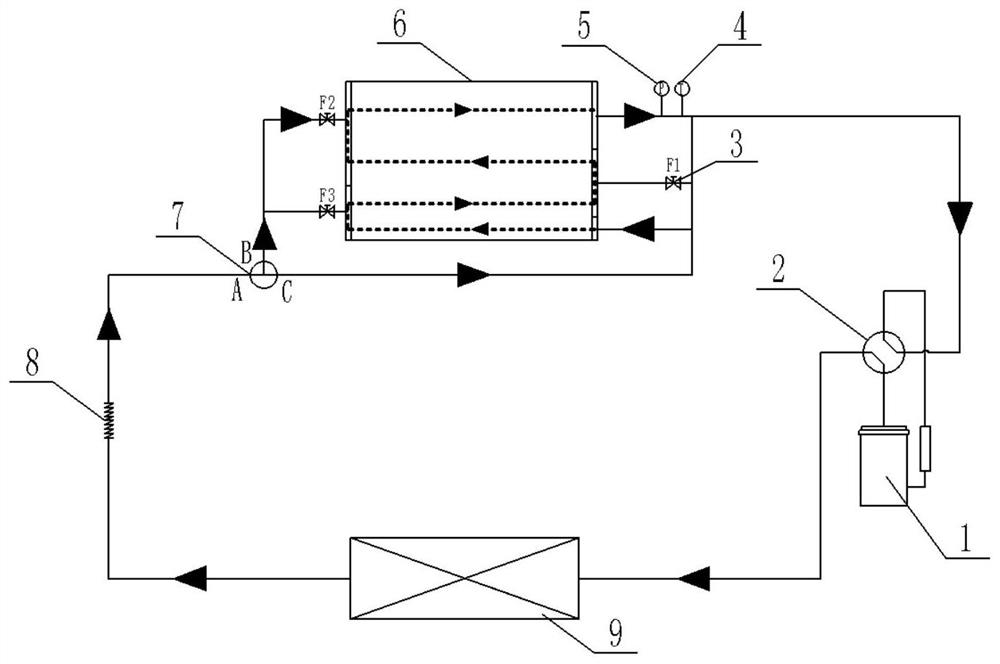
[0041] This implementation mode provides a control method for realizing the uniform flow distribution of the outdoor microchannel heat exchanger by replenishing liquid in the heating mode, such as figure 2 In the circulatory system shown, the names of the system components are as follows:

[0042]Among them, 1 is a compressor, 2 is a four-way valve, 3 is a stop valve (including the first stop valve F1, the second stop valve F2 and the third stop valve F3), 4 is a temperature gauge, 5 is a pressure gauge, 6 is an outdoor micro-channel heat exchanger, 7 is a flow distributor, 8 is a throttling device (no throttling effect, only plays the role of flow distribution), and 9 is an indoor heat exchanger.

[0043] Such as figure 2 As shown, in the cooling mode, after the refrigerant flows out from the compressor exhaust port, it enters the heat exchanger from the upper end of the outdoor micro-channel heat exchanger. The lower end of the heater flows out (as shown by the dotted li...

Embodiment 2

[0052] Taking a 9K split model as an example, the condenser uses a parallel micro-channel heat exchanger, and the capacity and energy efficiency are tested under three working conditions: rated cooling, rated heating (high temperature) and rated heating (low temperature) respectively (see Table 1) Compared with the performance of the non-replenishment air-conditioning system, under the rated heating (high temperature) and rated heating (low temperature) conditions, the capacity of the refilling air-conditioning system is increased by 10.8% and 19.1%, respectively, and the energy efficiency is increased by 3.9%. and 11.4%. The lower the outer working condition, the more obvious the contrast enhancement effect.

[0053] The fluid replenishment air conditioning system in the present invention is in the same flow process as the original non-fluid replenishment air conditioning system under the rated cooling condition, so the performance test conditions are comparable.

[0054] Ta...


PUM


Abstract

The invention belongs to the technical field of air conditioners, and discloses a fluid compensation type air conditioning system, a control method, computer equipment and a terminal. Under a heating mode, a high-temperature refrigerant discharged from a compressor enters an evaporator to exchange heat, and flows into a flow distributor through a throttling device; at an initial moment, a B-direction channel of the flow distributor is closed, so that all refrigerant flows out from a C-direction channel, enters from the lower end of a micro-channel heat exchanger to reversely circulate in an S-shaped mode, and flows out from the upper end of the heat exchanger; a pressure measuring meter and a temperature measuring meter are arranged at the outlet to detect pressure and temperature at the outlet every 30s; and a saturated temperature value Tpn is calculated according to a measured saturated pressure value Pn, and a test value Tn is compared with the calculated value Tpn. Heating performance under the heating mode of the micro-channel heat exchanger can be improved, so that the problem that a micro-channel is liable to frost is solved, continuous heating is realized, heating comfort is improved, and a frosting condition of the air conditioner is effectively improved.

Description

technical field [0001] The invention belongs to the technical field of air conditioning, and in particular relates to a liquid replenishing air conditioning system, a control method, computer equipment and a terminal. Background technique [0002] At present, the micro-channel heat exchanger has become a system component adopted by many air-conditioning companies due to its advantages of compact structure, light weight, low cost, high heat exchange efficiency and strong pressure resistance. However, in the heat pump cycle, on the one hand, due to the The fins of the heat exchanger have poor drainage. On the other hand, the heating capacity and energy efficiency are low due to the small diameter of the micro-channel, long process flow and large pressure loss, and it is very prone to frost and ice. This is one of the main reasons why microchannel heat exchangers cannot completely replace tube-fin heat exchangers. Therefore, improving the shunt effect of micro-channel heat exc...

Claims


Application Information

Patent Timeline
Patent Type & Authority Applications(China)
IPC IPC(8): F24F11/42F24F11/70F25B13/00F25B41/40F25B49/02F25B47/02F24F140/12F24F140/20
Inventor 李丽霞宋美琪冯家杰
Owner GREE ELECTRIC APPLIANCES INC
Why Eureka
Eureka Blog
Learn More