
Rail transportation equipment braking device utilizing magnetic attraction principle

A technology of rail transportation and braking devices, which is applied in the direction of transportation and packaging, brakes interacting between braking elements and rails, and railway braking systems. Failure and other issues

Inactive Publication Date: 2021-04-20
宣君
View PDF0 Cites 0 Cited by
  • Summary
  • Abstract
  • Description
  • Claims
  • Application Information

AI Technical Summary

Problems solved by technology

[0002] The brake of the rail transport vehicle is an essential device to ensure safe operation. The existing brake is generally a braking method in which the brake hook is hinged on the piston rod or the movable push rod through the middle hole to form a caliper brake hook. Double-sided braking with clamping on both sides. This kind of brake hook can be opened to the two outer sides and lifted above the track surface. It is suitable for ordinary tracks and can pass through track switches, but it also has high installation accuracy. When there are too many brake cars When the vehicle deviates from the track, the brake hook cannot grasp the track or cannot grasp the track surface in a wide range when braking, and the brake failure or insufficient braking occurs. Therefore, we propose a magnetic Suction principle rail transport equipment braking device

Method used


Image

  • Rail transportation equipment braking device utilizing magnetic attraction principle
  • Rail transportation equipment braking device utilizing magnetic attraction principle
  • Rail transportation equipment braking device utilizing magnetic attraction principle

Examples


Embodiment Construction

[0021] The following will clearly and completely describe the technical solutions in the embodiments of the present invention with reference to the accompanying drawings in the embodiments of the present invention. Obviously, the described embodiments are only some, not all, embodiments of the present invention. Based on the embodiments of the present invention, all other embodiments obtained by persons of ordinary skill in the art without making creative efforts belong to the protection scope of the present invention.

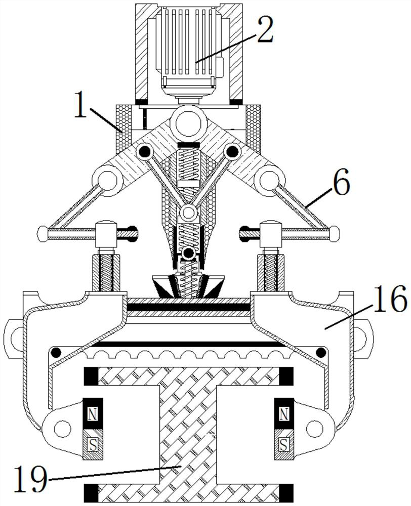
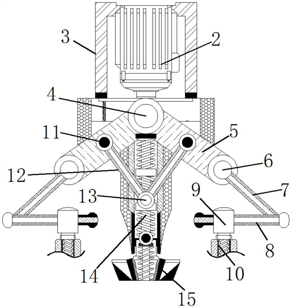
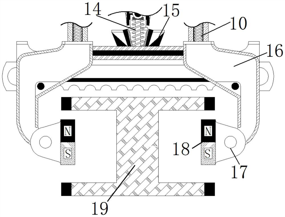
[0022] see Figure 1-4 , a braking device for rail transportation equipment using the principle of magnetic attraction, comprising a device main body 1, a trigger motor 2 is fixedly installed inside the device main body 1, a protective cover 3 is fixedly installed on the outside of the trigger motor 2, and the outside of the trigger motor 2 is fixed Connected with the drive shaft 4, the outside of the drive shaft 4 is fixedly connected with one end of the shaf...


PUM


Abstract

The invention relates to the technical field of railway transportation, and discloses a rail transportation equipment brake device utilizing a magnetic attraction principle. The device comprises a device main body, a trigger motor is fixedly mounted in the device main body, a protective sleeve is fixedly mounted on the outer side of the trigger motor, and a driving shaft center is fixedly connected to the outer side of the trigger motor; the outer side of the driving shaft center is fixedly connected with one end of a shaft rod, the other end of the shaft rod is fixedly connected with a bearing shaft center, the outer side of the bearing shaft center is fixedly connected with one end of a connecting rod, the other end of the connecting rod is fixedly connected with one end of an adapter rod, and the other end of the adapter rod is fixedly connected with a rotating grinding center. According to the rail transportation equipment braking device utilizing the magnetic attraction principle, due to the fact that the rail is made of steel, the electromagnetic blocks are fixedly installed on the inner sides of the clamping blocks, the electromagnetic blocks synchronously attract the rail based on the magnetic attraction force, and therefore, the purpose of braking deceleration is achieved.

Description

technical field [0001] The invention relates to the technical field of railway transportation, in particular to a braking device for rail transportation equipment using the principle of magnetic attraction. Background technique [0002] The brake of the rail transport vehicle is an essential device to ensure safe operation. The existing brake is generally a braking method in which the brake hook is hinged on the piston rod or the movable push rod through the middle hole to form a caliper brake hook. Double-sided braking with clamping on both sides. This kind of brake hook can be opened to the two outer sides and lifted above the track surface. It is suitable for ordinary tracks and can pass through track switches, but it also has high installation accuracy. When there are too many brake cars When the vehicle deviates from the track, the brake hook cannot grasp the track or cannot grasp the track surface in a wide range when braking, and the brake failure or insufficient brak...

Claims


Application Information

Patent Timeline
IPC IPC(8): B61H7/08B61H7/12
Inventor 宣君
Owner 宣君
Learn More