Electric vehicle charging pile suitable for low-temperature environment
A technology for electric vehicles and low-temperature environments. It is applied in the direction of electric vehicle charging technology, electric vehicles, charging stations, etc. It can solve the problems of easy water ingress, difficult touch screen operation, short circuit, etc., and achieve the effect of easy water addition and stable rotation
- Summary
- Abstract
- Description
- Claims
- Application Information
AI Technical Summary
Problems solved by technology
Method used
Image
Examples
Embodiment 1
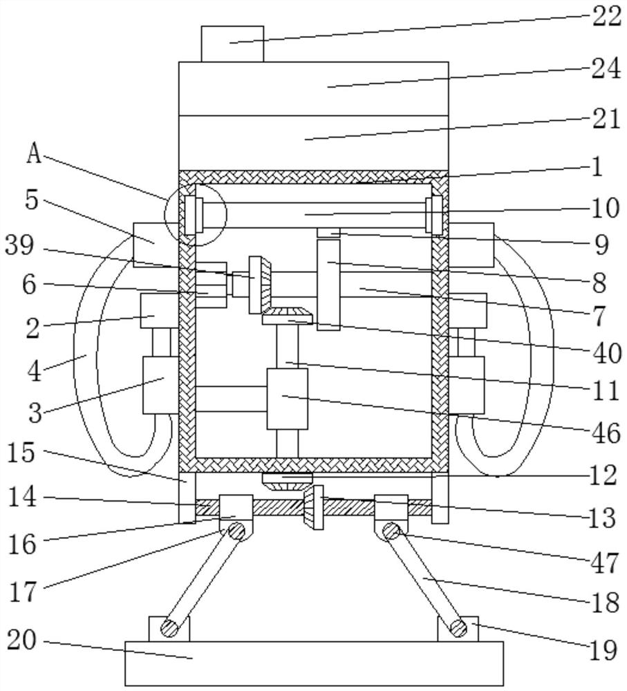
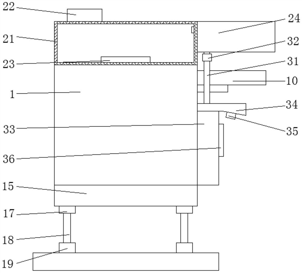
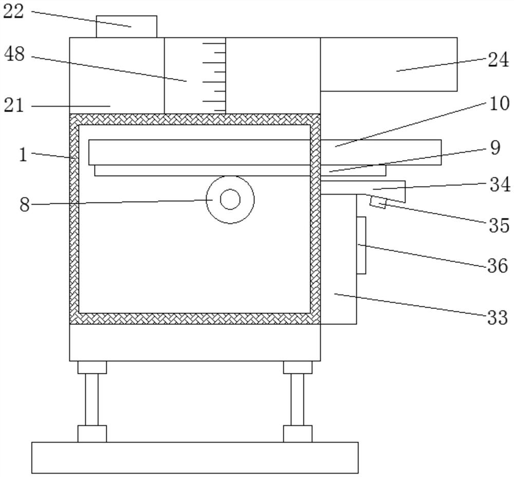
[0033] see Figure 1-8According to an embodiment of the present invention, a charging pile suitable for electric vehicles in a low-temperature environment includes a charging pile body 1, and storage tanks 2 are fixedly connected to both sides of the charging pile body 1, and a storage tank 2 is placed inside the storage tank 2. A charging gun 3, the bottom end of the charging gun 3 is fixedly connected with a charging line 4, and the end of the charging line 4 away from the charging gun 3 is fixedly connected with a current protector 5, and the current protector 5 is connected with the charging The pile body 1 is fixedly connected, the inner wall of one side of the charging pile body 1 is fixedly connected with a motor one 6, the output shaft of the motor one 6 is fixedly connected with a rotating shaft 7, and the surface of the rotating shaft 7 is fixedly connected with a main gear 8, The top of the main gear 8 is meshed with a rack 9, and the top of the rack 9 is fixedly co...
Embodiment 2
[0036] see figure 1 , 6 , 7. For the sliding mechanism, the sliding mechanism includes a sliding groove 37 and a sliding block 38. The inner walls of both sides of the charging pile body 1 are provided with sliding grooves 37, and the inside of the sliding groove 37 is slidingly connected with sliding Block 38, the slider 38 is fixedly connected with the rain shield 10, for the transmission mechanism, the transmission mechanism includes a bevel gear three 39 and a bevel gear four 40, and the surface of the rotating shaft 7 is fixedly connected with a bevel gear Three 39, the bottom end of the bevel gear three 39 is meshed with a bevel gear four 40, the bevel gear four 40 is fixedly connected with the threaded rod 14, for the suction mechanism, the suction mechanism includes a suction pipe 41 and check valve 2 42, a suction pipe 41 is connected between the piston cylinder 26 and the water tank 21, and a check valve 2 42 is installed on the suction pipe 41.
[0037] Through th...
Embodiment 3
[0039] see Figure 3-5 , for the drive mechanism, the drive mechanism includes a motor two 43 and a movable rod 44, the top inner wall of the fixed box 24 is fixedly connected with a motor two 43, and the output shaft of the motor two 43 is fixedly connected with a movable rod 44, The bottom end of the movable rod 44 is fixedly connected with the cam 25. For the control mechanism, the control mechanism includes a controller 45, and a controller 45 is installed on one side of the mounting plate 33. The touch screen 36 is connected to the Both the first motor 6 and the second motor 43 are electrically connected to the controller 45 , and for the water tank 21 , a glass observation window 48 is installed on the outside of the water tank 21 .
[0040] Through the above solution of the present invention, the glass observation window 48 is provided, which can facilitate the staff to observe the water level in the water tank 21, thereby facilitating water addition.
PUM
 Abstract
Description
Claims
Application Information
 - Generate Ideas
- Intellectual Property
- Life Sciences
- Materials
- Tech Scout
- Unparalleled Data Quality
- Higher Quality Content
- 60% Fewer Hallucinations
Browse by: Latest US Patents, China's latest patents, Technical Efficacy Thesaurus, Application Domain, Technology Topic, Popular Technical Reports.
© 2025 PatSnap. All rights reserved.Legal|Privacy policy|Modern Slavery Act Transparency Statement|Sitemap|About US| Contact US: help@patsnap.com


