
Inner wall machining equipment with positioning and supporting structure for equipment part production

A technology for positioning support structures and processing equipment, applied in the field of parts production, can solve problems such as easy shaking of grinding devices or parts, physical exertion of operators, and reduced accuracy of parts, so as to maintain stability, reduce physical exertion, and improve accuracy Improved effect

Inactive Publication Date: 2021-04-20
叶有弟
View PDF0 Cites 1 Cited by
  • Summary
  • Abstract
  • Description
  • Claims
  • Application Information

AI Technical Summary

Problems solved by technology

[0004] The purpose of the present invention is to solve the problem in the prior art that when the operator holds the parts for a long time, the operator will consume a lot of physical strength, and the operator cannot leave the grinding device and the operator during the entire processing of the parts. During long-time processing, it is prone to fatigue, which will easily cause the grinding device or parts to shake easily, resulting in the problem of reduced accuracy of the parts during processing. A kind of inner wall processing equipment with positioning support structure for the production of equipment parts is proposed

Method used


Image

  • Inner wall machining equipment with positioning and supporting structure for equipment part production
  • Inner wall machining equipment with positioning and supporting structure for equipment part production
  • Inner wall machining equipment with positioning and supporting structure for equipment part production

Examples


Embodiment Construction

[0031] The following will clearly and completely describe the technical solutions in the embodiments of the present invention with reference to the accompanying drawings in the embodiments of the present invention. Obviously, the described embodiments are only some, not all, embodiments of the present invention. Based on the embodiments of the present invention, all other embodiments obtained by persons of ordinary skill in the art without making creative efforts belong to the protection scope of the present invention.

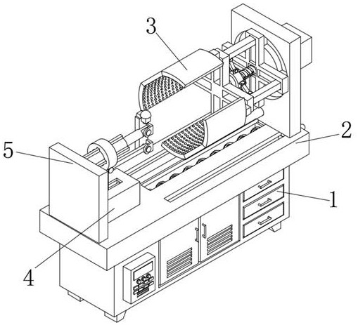
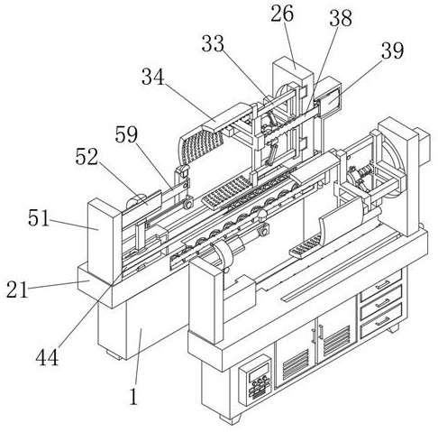
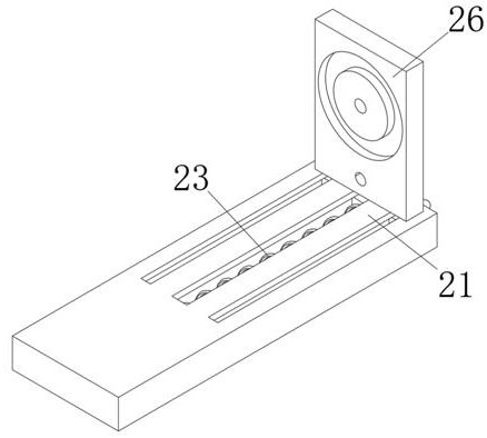
[0032] Please refer to Figure 1-10 , the present invention provides a technical solution: an inner wall processing equipment with a positioning support structure for the production of equipment parts, including a processing device main body 1, a moving mechanism 2 is arranged on the surface of the processing device main body 1, and a moving mechanism 2 is arranged inside the moving mechanism 2 The fixing mechanism 3, the fixing mechanism 3 includes a third co...


PUM


Abstract

The invention relates to the technical field of part production, in particular to inner wall machining equipment with a positioning and supporting structure for equipment part production. The equipment comprises a machining device main body, a moving mechanism is arranged on the surface of the machining device main body, a fixed mechanism is arranged in the moving mechanism, and the fixed mechanism comprises a third connecting block; and the third connecting block is inserted into the moving mechanism. By arranging a fixed rotating rod and a limiting rotating ring, fixed clamping plates can drive a part to move on the surface of the machining device main body by rotating the fixed rotating rod, machining of the part is facilitated, meanwhile, the fixed clamping plates can get close to each other by rotating the limiting rotating ring, and the part can be clamped and limited conveniently; and an operator does not need to perform holding and limiting for a long time, the physical exhaustion of the operator is reduced, and meanwhile, the operator does not need to watch over for a long time, so that the production efficiency of the part is greatly improved, and the production cost of the part is reduced.

Description

technical field [0001] The invention relates to the technical field of parts production, in particular to an inner wall processing equipment with a positioning support structure for the production of equipment parts. Background technique [0002] Parts are the basic elements of a machine, and can be broadly divided into two categories: one is the parts that can be used in various machines, called general-purpose parts; the other is used in certain types of machines The parts obtained are called special parts; in addition, the combination of parts composed of some cooperative parts is called a component or assembly. After the equipment parts are produced, the parts need to be further processed, mainly the inside and outside of the parts. , Grinding and polishing the inside and outside of the part. [0003] When the existing equipment parts are produced, the inside of the parts needs to be polished and polished. When the grinding device is in use, it is generally necessary fo...

Claims


Application Information

Patent Timeline
Patent Type & Authority Applications(China)
IPC IPC(8): B24B19/00B24B41/06B24B47/00B24B47/12B24B47/20
Inventor 叶有弟
Owner 叶有弟
Learn More